


Atmospheric Technology
13
5. Programming the Model 8000
The Model 8000 uses eight function tabs to allow the operator to enter or retrieve
information from the sampler
: Time/date, Set-up, Schedules, Data, Leak
Check
,
SOP, Manual
, and
Advanced
.
Time/date
is used to enter the current time and
date.
Set-up
is used to configure the sampler and store sampling parameters.
Sampling schedules are entered through the
Schedules
tab. Data can be displayed
or downloaded to a jump drive using the
Data
tab. Cartridges are manually leak
checked with the
Leak Check
tab. The
SOP
tab uses a standard operating
procedure to install and leak check the cartridges and program sampling schedules.
In
Manual
mode, the hardware can be uniquely activated to allow checkout and
troubleshooting. The system configuration and advance parameters are entered
using the
Advanced
tab.
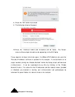
5.1 Time/Date
The time and date that is stored in the Model 8000 can be changed using the
Time/Date
tab. When this tab is touched, the operating system data and time
selection screen will appear. Once the changes have been made, pressing the
OK
button in the upper right corner of this window will bring back the main screen that
should show the correct day of the week, date, and time.
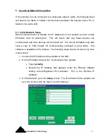
5.2 Setup
The
Setup
tab is used to input cartridge operating parameters, , enable software
updates, and calibrate the touch screen. When the
Setup
tab is touched, a green
screen appears which allows the operator to change the following parameters for
cartridge sampling:
Setup Parameters
Ch.1 MFC Set Point
The sampling flow rate for the Channel 1 cartridge is specified in this box.
Summary of Contents for 8000
Page 2: ......
Page 4: ...ii Atmospheric Technology ...
Page 8: ...2 Atmospheric Technology ...
Page 14: ...8 Atmospheric Technology ...
Page 18: ...12 Atmospheric Technology ...
Page 30: ...24 Atmospheric Technology ...
Page 39: ...Atmospheric Technology 33 Appendix A Schmatics ...
Page 40: ...34 Atmospheric Technology ...
Page 41: ...1 Model 2200V11 Interface Board Schematic 1 sch 7 ...
Page 42: ......
Page 43: ...Model 2200V11 Interface Board Schematic 2 sch 2 7 ...
Page 44: ......
Page 45: ...Model 2200V11 Interface Board Schematic 3 sch 3 7 ...
Page 46: ......
Page 47: ...Model 2200V11 Interface Board Schmatic 4 sch 4 7 ...
Page 48: ......
Page 49: ...Model 2200V11 Interface Board Schematic 5 sch 5 7 ...
Page 50: ......
Page 51: ...Model 2200V11 Interface Board Schematic 6 sch 6 7 ...
Page 52: ......
Page 53: ...Model 2200V11 Interface Board Schematic 7 sch 7 7 ...
Page 54: ......
Page 55: ...Atmospheric Technology 49 Appendix B Manual for Mass Flow Controller ...
Page 56: ......