


20
Atmospheric Technology
A
Manual
tab is provided to allow the operator to activate any solenoid valve or
pump. This mode is useful in troubleshooting and testing individual components. In
addition, the flow set point of each mass flow controller can be individually set. Upon
leaving the manual mode screen, all settings revert to the values used in automatic
mode
.
NOTE
: All values displayed in Manual Mode are raw signal values and are
NOT corrected by the calibration constants entered in the Set-Up screen.
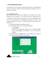
5.9 Advanced
Additional settings can be stored in the Advanced Setup section that is accessed
through the
Advanced
tab. This portion of setup should only be used by individuals
familiar with the operation and calibration of components used in the Model 8000.
Changing the values in the Advanced Setup will alter the accuracy of the instrument.
Several of the parameters are hardware dependent. These are set at the factory
and require a password to be entered to be changed.
Mass Flow Controller Calibration
The calibration of the mass flow controllers can be changed by entering the
appropriate slope and intercept for each mass flow controller. See Appendix A.
Mass Flow Meter Range (password controlled)
If the full scale range of a mass flow controller is changed, the corresponding full-
scale range must be entered in the MFC Range box.
Heater Set Point
The set point of the ozone scrubber heater may be changed by replacing the value
in the box marked Heater Set Point. The normal set point is 50
°
C.
Summary of Contents for 8000
Page 2: ......
Page 4: ...ii Atmospheric Technology ...
Page 8: ...2 Atmospheric Technology ...
Page 14: ...8 Atmospheric Technology ...
Page 18: ...12 Atmospheric Technology ...
Page 30: ...24 Atmospheric Technology ...
Page 39: ...Atmospheric Technology 33 Appendix A Schmatics ...
Page 40: ...34 Atmospheric Technology ...
Page 41: ...1 Model 2200V11 Interface Board Schematic 1 sch 7 ...
Page 42: ......
Page 43: ...Model 2200V11 Interface Board Schematic 2 sch 2 7 ...
Page 44: ......
Page 45: ...Model 2200V11 Interface Board Schematic 3 sch 3 7 ...
Page 46: ......
Page 47: ...Model 2200V11 Interface Board Schmatic 4 sch 4 7 ...
Page 48: ......
Page 49: ...Model 2200V11 Interface Board Schematic 5 sch 5 7 ...
Page 50: ......
Page 51: ...Model 2200V11 Interface Board Schematic 6 sch 6 7 ...
Page 52: ......
Page 53: ...Model 2200V11 Interface Board Schematic 7 sch 7 7 ...
Page 54: ......
Page 55: ...Atmospheric Technology 49 Appendix B Manual for Mass Flow Controller ...
Page 56: ......