Switch View
Issue 2 April 1996
4-7
Switch View Hotspots
The central portion of the Switch View contains hotspots in the form of icons that
represent external devices and cabinets.
Each cabinet icon represents a particular cabinet on the PBX and depicts the
type of cabinet.
See Hotspots in Chapter 1 for an overview of hotspots.
Colored Borders
Each icon is surrounded by a border that is highlighted with the color that
represents the highest level of alarm. If the icon does not have a colored border,
there is no alarm.
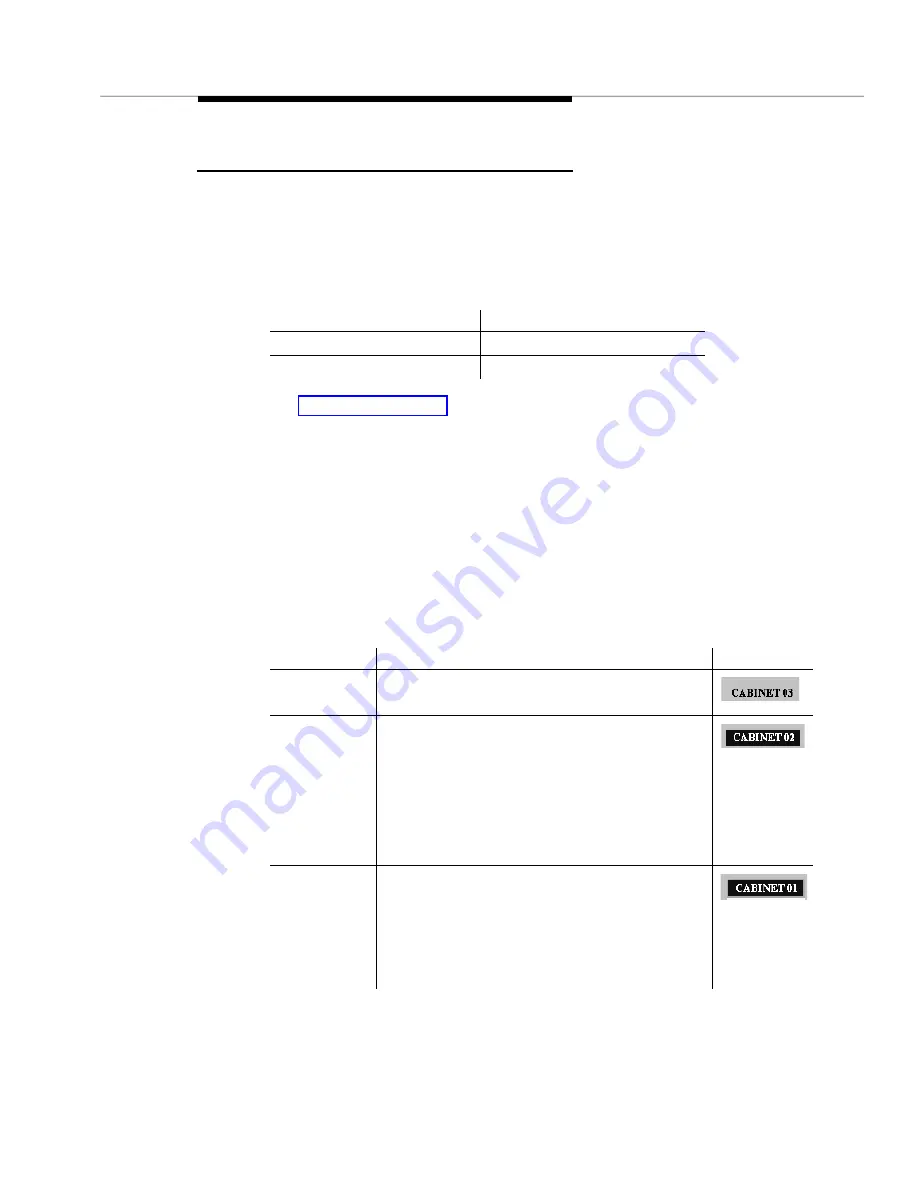
Icon Labels
A label displays above each icon in the hotspot area. Icon labels have the
following components:
If you click on this icon …
Then this screen displays …
External Device
External Devices
Cabinet
The appropriate Cabinet View
Component Description
Example
Name
Identifies the external device or cabinet
Background
color
Identifies cabinets with a circuit pack
mismatch.
If the cabinet does not contain any circuit
packs mismatches, the background color does
not display. (See example for Name.)
You can set the background color in the Circuit
Pack Mismatch Color field on the Setup screen.
Border
Identifies an external device or cabinet that
Fault Management includes in a report. This
border only displays if you request a report with
highlighting.
You can set the color for this border in the
Highlight Color field on the Setup screen.
Summary of Contents for OneVision DEFINITY G3 Fault Management and integration
Page 26: ...Introduction 1 14 Issue 2 April 1996 Figure 1 4 Trap Message for External Devices ...
Page 64: ...Port Information Issue 2 April 1996 4 21 Figure 4 6 Port Information Pooled Modem ...
Page 65: ...The Configuration Map 4 22 Issue 2 April 1996 Figure 4 7 Port Information Station ...
Page 66: ...Port Information Issue 2 April 1996 4 23 Figure 4 8 Port Information Data Module ...
Page 74: ...External Devices Issue 2 April 1996 4 31 Figure 4 10 External Devices View ...
Page 114: ...Report Builder 7 4 Issue 2 April 1996 Figure 7 1 Report Builder Screen ...


