


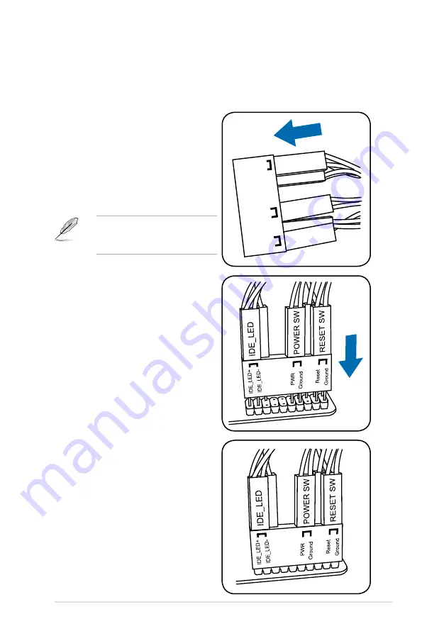
13. ASUS Q-Connector (system panel)
Use the ASUS Q-Connector to connect/disconnect the chassis front panel cables.
To install the ASUS Q-Connector:
1. Connect the front panel cables to the
ASUS Q-Connector.
Refer to the labels on the Q-
Connector to know the detailed pin
definitions, and then match them
to their respective front panel cable
labels.
The labels on the front panel
cables may vary depending on the
chassis model.
2. Install the ASUS Q-Connector to the
system panel connector, ensuring
the orientation matches the labels
on the motherboard.
3. The front panel functions are now
enabled. The figure shows the Q-
Connector is properly installed on
the motherboard.
IDE_LED
POWER SW
RESET SW
IDE_LED-
PWR
Reset
Ground
Ground
ROG Maximus II GENE
2-43
Summary of Contents for Maximus II Gene
Page 1: ...Motherboard Maximus II GENE ...
Page 30: ...2 2 Motherboard overview 2 2 1 Motherboard layout 2 6 Chapter 2 Hardware information ...
Page 57: ...Connect to 5 1 channel Speakers Connect to 7 1 channel Speakers ROG Maximus II GENE 2 33 ...
Page 120: ...3 46 Chapter 3 BIOS setup ...
Page 164: ...ROG Maximus II GENE Chapter summary 5 5 1 ATI CrossFireX technology 5 1 ...
Page 169: ...A Appendix Debug code table The Appendix lists the debug code table for the LCD Poster ...
Page 170: ...ROG Maximus II GENE Chapter summary A Debug code table A 1 ...
Page 174: ...A 4 Appendix Debug code table ...


