background image

GigaX Series L2 Managed Switch User Guide 

67 

5.1 

Power On Self Test 

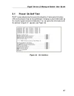
POST is executing during the system booting time. It tests system memory, 
LED and hardware chips on the switchboard. It displays system information as 
the result of system test and initialization. You can ignore the information until 
the prompt, “(

GigaX) %

”, appears (see Figure 42). 


Figure 42.  CLI interface 

Summary of Contents for GigaX 2124X

Page 1: ...GigaX Series Layer 2 Managed Switch User Guide ...

Page 2: ...s or conditions of merchantability or fitness for a particular purpose In no event shall ASUS its directors officers employees or agents be liable for any indirect special incidental or consequential damages including damages for loss of profits loss of business loss of use or data interruption of business and the like even if ASUS has been advised of the possibility of such damages arising from a...

Page 3: ...ipment does cause harmful interference to radio or television reception which can be determined by turning the equipment off and on the user is encouraged to try to correct the interference by one or more of the following measures Reorient or relocate the receiving antenna Increase the separation between the equipment and receiver Connect the equipment to an outlet on a circuit different from that...

Page 4: ...ail tmd1 asus com Web Site usa asus com Technical Support Support Fax 1 502 933 8713 General Support 1 502 995 0883 Notebook Support 1 510 739 3777 x5110 Support Email tsd asus com ASUS COMPUTER GmbH Germany and Austria Address Harkort Str 25 D 40880 Ratingen BRD Germany General Fax 49 2102 9599 31 General Email sales asuscom de for marketing requests only Technical Support Support Hotlines Compon...

Page 5: ...nting the switch on a rack 18 3 2 Part 2 Setting up the switch 19 3 2 1 Connect the console port 19 3 2 2 Connect to the computers or a LAN 19 3 2 3 Attach the RPS module 19 3 2 4 Attach the power adapter 19 3 3 Part 3 Basic switch setting for management 21 3 3 1 Setting up through the console port 21 3 3 2 Setting up through the Web interface 23 4 1 Log into Web user interface 25 4 2 Functional l...

Page 6: ...ses 44 4 5 8 Static Addresses 46 4 5 9 Tagged VLAN 47 4 5 10 Default Port VLAN and CoS 49 4 5 11 CoS Queue Mapping 50 4 6 SNMP 51 4 6 1 Community Table 51 4 6 2 Host Table 52 4 6 3 Trap Setting 53 4 6 4 VACM Group 53 4 6 5 VACM View 54 4 6 6 USM User 56 4 7 Security 58 4 7 1 Port Access Control 58 4 7 2 Dial In User 59 4 7 3 RADIUS 60 4 8 VCT 62 4 9 Statistics Chart 63 4 9 1 Traffic Comparison 63 ...

Page 7: ... 2 Physical Interface Commands 73 5 3 3 Bridge Commands 74 5 3 4 SNMP 82 5 3 5 Security Commands 90 CLI command security sshkey show 93 5 4 Miscellaneous Commands 94 6 1 IP Addresses 95 6 1 1 Structure of an IP address 95 6 1 2 Network classes 97 6 2 Subnet masks 98 7 1 Diagnosing problems using IP utilities 100 7 1 1 ping 100 7 1 2 nslookup 102 7 2 Replacing defective fans 103 7 3 Simple fixes 10...

Page 8: ...nfiguration manager login screen 25 Figure 9 Home page 26 Figure 10 Top frame 27 Figure 11 Expanded Menu List 28 Figure 12 Management 30 Figure 13 IP Setup 31 Figure 14 Administration 32 Figure 15 Firmware Upgrade 34 Figure 16 Physical Interface 36 Figure 17 Spanning Tree 38 Figure 18 Link aggregation 40 Figure 19 Mirroring page 41 Figure 20 Static Multicast 42 Figure 21 IGMP Snooping 43 Figure 22...

Page 9: ...s Control 59 Figure 35 Dial In user 60 Figure 36 RADIUS 61 Figure 37 VCT 62 Figure 38 Traffic comparison 63 Figure 39 Error group 64 Figure 40 Historical Status 64 Figure 41 Save Configuration 65 Figure 42 CLI interface 67 Figure 43 Boot ROM Command Mode 68 Figure 44 SYS commands 71 Figure 45 Using the ping utility 101 Figure 46 Using the nslookup utility 102 Figure 47 Loosening the thumbscrew 103...

Page 10: ...el labels and LEDs 15 Table 2 Rear panel labels 16 Table 3 Technical specifications 17 Table 4 LED Indicators 21 Table 5 Port color description 27 Table 6 Commonly used buttons and icons 29 Table 7 Boot ROM commands 69 Table 8 IP address structure 96 Table 9 Troubleshooting 105 ...

Page 11: ...m factor SFP Gigabit interface converter GBIC slots 802 1D transparent bridge spanning tree protocol 8K MAC address cache with hardware assisted aging 802 3x flow control 802 1Q based tagged VLAN up to 255 VLANs 802 1p class of service 4 queues per port IGMP snooping support 802 3ad link aggregation manual and LACP up to 31 trunk groups Port Mirroring 802 1w RSTP 802 1x and RADIUS RMON support 4 g...

Page 12: ...are used to present the parameters for the command line interpreter Boldface type text is used for items you select from menus and drop down lists and text strings you type when prompted by the program 1 2 3 Symbols This document uses the following icons to call your attention to specific instructions or explanations Note Provides clarification or additional information on the current topic Defini...

Page 13: ...ckage comes with the following items GigaX 2124X 24 port L2 managed switch AC Power cord Null modem cable for console interface DB9 Rack installation kit two brackets with six 6 32 screws USB cable for console interface Installation CD ROM User Manual Quick installation guide Figure 1 GigaX L2 managed switch package contents ...

Page 14: ...GigaX Series L2 Managed Switch User Guide 14 2 2 Front Panel The front panel includes LED indicators that show the system RPS fan and port status Figure 2 Front panel ...

Page 15: ...nd the switch is powered by RPS RPS Off No power at all system LED is also off RPS does not work properly or not installed system LED is on Green On Both fans are working properly FAN Amber On Both or either one of the fans stopped Green On Link RJ 45 or SFP is present port is enabled Flashing Data is being transmitted received 10 100 1000 port status Off No Ethernet link Green On 1000Mbps Amber O...

Page 16: ... power connections Figure 3 Rear panel Table 2 Rear panel labels No Label Description 1 Power Connector Connects to the supplied power cord 2 FAN1 FAN2 Replaceable system fans 3 Console USB USB port for console management 4 Console RS232 RS 232 serial port for console management 5 RPS Redundant Power Supply connector ...

Page 17: ...ion Power 100 240V AC 2 5A 50 60Hz 90 watts Input Output Redundant Power Supply RPS 100 240V AC 1 8A 50 60Hz 12V DC 12 5A Operating Storage Temperature 10 to 50 14 to 122 40 70 40 to 158 Humidity 15 to 90 0 to 95 Environmental Ranges Altitude up to 10 000 ft 3 000m 40 000 ft 12 000m Dimensions Voltage and Current Speed Replaceable Fans 40 x 40 x 20 mm 12VDC 0 13A 8200RPM ...

Page 18: ...ss for the switch Default gateway for the network Network mask for this network 3 1 Part 1 Installing the hardware Connect the device to the power outlet and your computer or network Figure 4 illustrates the hardware connections 3 1 1 Installing the switch on a flat surface The switch should be installed on a level surface that can support the weight of the switches and their accessories Attach fo...

Page 19: ...es You can use either the crossover or straight through Ethernet cable to connect computers hubs or switches Use a twisted pair Category 5 Ethernet cable to connect the 1000BASE T port Otherwise the link speed can not reach 1Gbps 3 2 3 Attach the RPS module Connect your RPS module to the RPS jack and make sure the other end of the RPS is connected to the power cord Connect to the power cord to a g...

Page 20: ...GigaX Series L2 Managed Switch User s Guide 20 Figure 4 Overview of Hardware Connections Console Management Expansion hub switch LAN computers RPS RS 232 USB Cat 5 Ethernet cables ...

Page 21: ... settings for your switch You can manage the switch using the following methods Web interface the switch has a set of pages to allow to you manage it using Java enabled IE5 0 or higher version Command Line Interface use console port to manage the switch 3 3 1 Setting up through the console port 1 Use the supplied crossover RS 232 cable to connect to the console port on the back of the switch This ...

Page 22: ... can change the password at any time through CLI see section 5 3 1 To protect your switch from unauthorized access you must change the default password as soon as possible 6 Follow these steps to assign an IP address to the switch a Type net interface ip sw0 your ip address your network mask For example if your switch IP is 192 168 10 1 and the network mask is 255 255 255 0 Then you should type ne...

Page 23: ...e to use Web interface because the default configuration for Web access authentication is disabled To secure the system configuration please enable the authentication function at the Administration page under System category Skip step 2 if the authentication is disabled 2 At any PC connected to the network that the switch can access open your Web browser Internet Explorer and type the following UR...

Page 24: ...t gateway then click 4 If your new address is different from the default the browser can not update the switch status window or retrieve any page This is normal You have to retype the new IP address in the address location box and press Enter The WEB link returns 5 To enable authentication for Web access click Administration on the menu list then select Enabled to start the protection A login wind...

Page 25: ...ace 1 From a PC open your web browser type the following in the web address or location box and press Enter http 192 168 1 1 This is the factory default IP address for the switch A login screen displays as shown in Figure 8 Figure 8 Configuration manager login screen 2 Enter your user name and password then click Use the following defaults the first time you log into the program You can change the...

Page 26: ...GigaX Series L2 Managed Switch User s Guide 26 The home page appears each time you log into the program See Figures 9 Figure 9 Home page ...

Page 27: ...scription Figure 10 Top frame Table 5 Port color description Port Color Description Green port Ethernet link is established Black No Ethernet link Amber port Link is present but port is disabled manually or by spanning tree Clicking on the port icon of the switch displays the port configuration in the lower right frame The left frame a menu frame as shown in Figure 11 contains all the features ava...

Page 28: ...GigaX Series L2 Managed Switch User s Guide 28 Figure 11 Expanded Menu List The right frame displays configuration pages or graphics for the statistics See section 4 3 for details ...

Page 29: ...ed buttons and icons The following table describes the function for each button and icon used in the application Table 6 Commonly used buttons and icons Button Icon Function Stores any changes you have made on the current page Adds the existing configuration to the system e g a static MAC address or a firewall ACL rule and etc Modifies an existing entry Modifies the existing configuration in the s...

Page 30: ... Management The Management page contains the following information Model Name product name MAC Address switch MAC address System Name user assigned name to identify the system editable System Contact editable System Location editable To save any changes and make it effective immediately click Use to refresh the setting as shown in Figure 12 Figure 12 Management ...

Page 31: ... contains the following editable information VLAN ID Specify a VLAN ID to system management interface It is necessary to be within the same VLAN for management usages IP Address assign a static IP address to the switch management interface Network Mask Default Gateway To save any changes and make it effective immediately click Use to refresh the setting as shown in Figure 13 Figure 13 IP Setup ...

Page 32: ...word protection The default setting for web access does not require any authentication To save any changes and make it effective immediately click Use to refresh the setting as shown in Figure 18 When you enable the password protection you have to login again immediately You can change the password at any time through the CLI interface Figure 14 Administration ...

Page 33: ...ision number Boot ROM Version shows the version of the boot code Firmware Version shows the current running firmware version This number will be updated after the firmware update Enter the firmware location into the firmware space directly or click to choose the file name of the firmware from prompt window Click to update the switch firmware See Figure 15 for reference Clicking the upload button l...

Page 34: ...GigaX Series L2 Managed Switch User s Guide 34 Figure 15 Firmware Upgrade ...

Page 35: ...lowing information for each port a Link status the link speed and duplex for an existing link otherwise link is down b State the STP state c Admin the setting value to disable or enable the port d Mode the setting value for link speed and duplex mode e Flow Control the setting value to enable or disable 802 3x flow control mechanism Select the corresponding port number and configure the port setti...

Page 36: ...GigaX Series L2 Managed Switch User s Guide 36 Figure 16 Physical Interface ...

Page 37: ...uration BPDU Max Age a timeout value to be used by all Bridges in the LAN Forward Delay a timeout value to be used by all bridges in the LAN Bridge Priority the switch priority in the LAN The third part is the port setting It contains a display window to show the current configuration for each port You click to change the port setting for STP RSTP The following fields are available Port select the...

Page 38: ... point link Otherwise it is a shared link Point to point link may have less convergence time Auto is recommended in most cases Click to make the settings effective Click to refresh the settings to current value Figure 17 Spanning Tree 4 5 2 Link Aggregation The page configures the link aggregation group port trunking The switch can have 6 link aggregation groups Show Trunk Select Add a new Trunk f...

Page 39: ...age then click You have to check the runtime link speed and duplex mode to make sure the trunk is physically active Go to Physical Interface and check the link mode in the runtime status window for the trunk ports If all the trunk members are in the same speed and full duplex mode then the trunk group is set up successfully If one of the members is not in the same speed or full duplex mode the tru...

Page 40: ...ists of port 1 and 2 If the VLAN of port 1 changes the VLAN of port 2 also changes with port 1 Figure 18 Link aggregation 4 5 3 Mirroring Mirroring together with a network traffic analyzer helps you monitor network traffics You can monitor the selected ports for egress or ingress packets Mirror Mode Enables or disables the mirror function for the selected group Monitor Port Receives the copies of ...

Page 41: ...ation group The monitor port can not operate as a normal switch port It does not switch packets or do address learning 4 ports are only supported for mirror egress port Click to make the setting send to the switch HTTP server Click to refresh the settings to current value Figure 19 Mirroring page ...

Page 42: ...All the ports in the group will forward the specified multicast packets to other ports in the group Show Group selects Add a new Group to enter a new entry Or select an existing group address to display MAC Address selects the multicast address VLAN selects the vlan group Click to make the setting effective Click to refresh the settings to current value Figure 20 Static Multicast ...

Page 43: ... does not work normally The switch only allows 256 layer 2 multicast group Figure 21 IGMP Snooping 4 5 6 Traffic Control Traffic control prevents the switch bandwidth from flooding packets including broadcast packets multicast packets The limit number is a threshold to limit the total number of the checked type packets For example if broadcast and multicast are enabled the total traffic amount for...

Page 44: ... it will age out from the address table if the address is not learned again during the age time User can set the age time by entering a valid number from 10 to 1 000 000 in seconds Then click on to save the new age value To make the configuration effective please go to Save Configuration page then click on You can look up MAC addresses by checking the port VLAN ID or and MAC address then click on ...

Page 45: ...GigaX Series L2 Managed Switch User Guide 45 Figure 23 Dynamic Address ...

Page 46: ... packet filtering when the MAC address appears in the packets as destination address source address or either of them Click on when you create a new static MAC address by the above information Then you will see the new added entry shows in the address window You can remove the existed address by selecting the entry with the mouse then clicking on The button updates the existed MAC address entries ...

Page 47: ... to two or more VLAN groups at the same time it will confuse the switch and cause flooding traffics To prevent it the switch only allows one untagged port belongs to one VLAN at the same time That is the untagged port belongs to the VLAN group which is called PVID and configured in the Default Port VLAN CoS page If you want to assign an untagged port from one VLAN to another you have to remove it ...

Page 48: ...GigaX Series L2 Managed Switch User s Guide 48 Figure 25 Tagged VLAN ...

Page 49: ... be tagged with this VLAN group ID CoS Class of Service value every untagged packet received from this port will be assigned to this CoS in the VLAN tagged Due to 4 internal traffic class mapping to 8 priority Only CoS value 0 2 5 7 are valid according to CoS Queue Mapping Click on to change the content in the port list window Click on to save the configuration To make the configuration effective ...

Page 50: ...ues for each port with a strict priority schedule That is each CoS value can map into one of the four queues The queue 4 has the highest priority to transmit the packets Click to save the configuration To make the configuration effective go to Save Configuration page then click Figure 27 Cos Queue Mapping ...

Page 51: ...ap Setting To provide more secure management and access control SNMPv3 is supported 4 6 1 Community Table You can type different community names and specify whether the community has the privilege to make a setting write access by checking the box Click to save the configuration permanently or to refresh the page Figure 28 Community Table ...

Page 52: ...Table This page links host IP address to the community name that is entered in Community Table page Type an IP address and select the community name from the drop down list Click to save the configuration permanently or to refresh the page Figure 29 Host Table ...

Page 53: ...Trap Setting 4 6 4 VACM Group VACM View based Access Control Model Group is used to configure the information of SNMPV3 VACM Group Group Name enter the security group name Read View Name enter the Read View Name that the Group belongs The related SNMP messages are Get GetNext GetBulk Write View Name enter the Write View Name that the Group belongs The related SNMP message is Set Notify View Name e...

Page 54: ... information Then you will see the new added entry shows in the group window You can remove the existed group by selecting the entry with the mouse then clicking on The button updates the existed VACM Group entries Click to save effectively Click to refresh the settings to current value To make the configuration effective please go to Save Configuration page then click on Figure 31 VACM Group 4 6 ...

Page 55: ...iew Mask that the View belongs Each bit in the mask represents the digit between the dots of View Subtree from left side Bit 0 means don t care Click on the when you create a new VACM View entry by the above information Then you will see the new added entry shows in the view window You can remove the existed views by selecting the entry with the mouse then clicking on The button updates the existe...

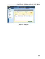
Page 56: ...ssword needs at least 8 characters or digits Priv Protocol enter the Priv Protocol that Engine ID and Name belong Only NoPriv DES can be chosen If the NoPriv is chosen there is no need to enter password Priv Password enter the password that the Priv Protocol belongs The password needs at least 8 characters or digits Click on the when you create a new USM User entry by the above information Then yo...

Page 57: ...GigaX Series L2 Managed Switch User Guide 57 Figure 33 USM User ...

Page 58: ...ion Once enabled the switch will try to authenticate the port user again when the re authentication time is up Reauthentication Time If Reauthentication is enabled this is the interval for the switch to re send authentication request to the port user see above Authentication Method RADIUS or Local database can be used to authenticate the port user Quiet Period If authentication failed either from ...

Page 59: ...Thus traffic from all hosts is allowed to pass Otherwise if force unauthorized is selected the selected port is blocked and no traffic can go through If Auto is selected the behavior of the selected port is controlled by 802 1x protocol All ports should be set to Auto under normal conditions Guest VLAN Specify a guest VLAN to clients that are not 802 1x capable Click to make the settings effective...

Page 60: ...ned to the 802 1x authenticated clients Please click to add the new user Click when you have finished the modifications Click when you want to remove the selected user Click to make the settings effective permanently Click to refresh the settings to current value Figure 35 Dial In user 4 7 3 RADIUS In order to use external RADIUS server the following parameters are required to be setup ...

Page 61: ...g to Authentication Server Key The key is used for communications between GigaX and the RADIUS server Confirm Authentication Key Re type the key entered above The VLAN of the RADIUS server connected to the switch must be the same as the VLAN of the system management interface Please click to make the settings permanent Click to refresh the settings to current value Figure 36 RADIUS ...

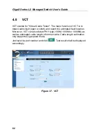
Page 62: ...tect cable fault open or short and report the estimated fault location Moreover VCT can also detect PHY type 100M 1000M or 10000M as well as estimated cable length of normal cable Cable length estimation only supports Giga speed mode Just select a port number and click Test result shall be displayed accordingly Figure 37 VCT ...

Page 63: ...e the statistics or ports by selecting Color Finally click on Draw to let the browser to draw the graphic chart Each new Draw will reset the statistics display 4 9 1 Traffic Comparison This page shows the one statistics item for all the ports in one graphic chart Specify the statistics item to display and click the Draw the browser will show you the update data and refresh the graphic periodically...

Page 64: ...Error group 4 9 3 Historical Status You can display information for different ports and statistics items in this chart Since this shows the history of the statistics information the chart can keep the old data even it is refreshed Figure 40 Historical Status ...

Page 65: ...fective after a successful save Sometimes you may want to reset the switch configuration you can click on to reset the configuration file to factory default Of course a system reboot will follow this restoration process You will lose all the configurations when you choose to restore the factory default configurations Figure 41 Save Configuration ...

Page 66: ...and help messages This is very useful when you are not familiar with the CLI commands The CLI mode times out when idle for 10 minutes You have to login again to enter CLI mode after the timeout All the CLI commands are case sensitive In order to make them easier to use you can enter into different category by typing the full command then this category becomes your working category Thereafter you d...

Page 67: ...cuting during the system booting time It tests system memory LED and hardware chips on the switchboard It displays system information as the result of system test and initialization You can ignore the information until the prompt GigaX appears see Figure 42 Figure 42 CLI interface ...

Page 68: ...shows dual images in the switch One firmware is in Slot 0 and the other firmware is in Slot 1 The later version will be selected to boot the system automatically Enter the key to show the help messages for all available commands Although the commands are helpful in some situation we STRONGLY suggest users not to use them if you don t know the command function Figure 43 Boot ROM Command Mode ...

Page 69: ...t IP address g NONE Load and execute firmware h NONE Display online help m mask Configure network mask You have to set up the terminal emulator with the same baud rate to make the work p NONE Display current configuration I R NONE System reboot s IP address Configure TFTP server IP address t NONE Toggle safe mode u File name Upload boot module firmware via network using TFTP protocol v NONE Displa...

Page 70: ...CLI mode The next user has to do login again with authorized user name and password 5 3 CLI Commands The switch provides CLI commands for all managed functions The command uses are listed in the categories as the WEB management interface This way you can follow the instructions and set up the switch correctly as easily as using WEB interface to configure the switch save command is used to save the...

Page 71: ...ed node CLI command sys contact system contact description If you put the contact description in the contact description field the switch contact information will be changed to the new one System Location Displays the physical location of the switch This is an RFC 1213 defined MIB object in System Group and provides the location information on the managed node CLI command sys location system locat...

Page 72: ... the switch CLI command net interface ip sw0 IP address netmask Default Gateway Displays the IP address of the default gateway This field is necessary if the switch network contains one or more routers CLI command net route static add destination subnet IP gateway netmask metric Password Protection is Enabled Disabled When the password protection is enabled the web interface will request a user na...

Page 73: ...he port on or off CLI command l2 port admin port number enable disable Mode Auto 10M Half 10M Full 100M Half 100M Full 1G Full Displays the current speed and duplex mode of the port The speed and duplex mode can be automatically detected when auto negotiation is enabled on a port CLI command l2 port autoneg port number enable disable CLI command l2 port speed port number 10 100 1000 CLI command l2...

Page 74: ...op Hello Time Forward Delay Max Age Bridge Priority Displays the current STP RSTP bridge parameters setting CLI command l2 stp bridge set Hello Time 1 10 seconds old Hello Time new Hello Time Max Age 6 40 seconds old Max Age new Max Age Forward Delay 4 30 seconds old Forward Delay new Forward Delay Bridge Priority 0 65535 old Bridge Priority new Bridge Priority Priority Path Cost Edge Port Point t...

Page 75: ... stp retrieve CLI command l2 stp bridge retrieve CLI command l2 stp port retrieve Show Trunk Displays a specific trunk group settings User can create a new trunk group by specify a unique trunk ID a trunk name description the port selection criterion rtag LACP mode enabled or disable and its trunk group member ports CLI command l2 trunk show trunk id rtag Sets traffic distribution algorithm 1 3 Th...

Page 76: ...up CLI command l2 trunk add trunk id port list CLI command l2 trunk remove trunk id port list LACP Action User can enable or disable LACP on a specific trunk group CLI command l2 trunk lacp action trunk id enable disable LACP System Priority User can assign the system priority for running LACP CLI command l2 trunk lacp syspri priority 1 65535 LACP Port Priority User can assign the port priority fo...

Page 77: ...cast groups that are presented in the multicast group table CLI command l2 mcast show Set Multicast Group Allows user to add or modify a static multicast group by specifying the MAC address VLAN ID Class of Service VLAN port members and its untagged port members Note that MAC address and VLAN ID combination is formed as an unique entry in multicast group table CLI command l2 mcast set mac address ...

Page 78: ...the previous saved settings from configuration file CLI command l2 igmp retrieve Broadcast Enabled Disabled Multicast Enabled Disabled Destination Lookup Failure Enabled Disabled User can limit the broadcast multicast and flooding due to destination lookup failed traffic rate by turning the traffic control on CLI command l2 rate set 1 bcast 2 mcast 3 dlf enable disable Limit Displays the current r...

Page 79: ... number CLI command l2 arl port port number Query by VLAN ID ARL entries existed in ARL table can be queried according to VLAN ID CLI command l2 arl vlan vlan id Query by MAC Address ARL entries existed in ARL table can be queried according to MAC address CLI command l2 arl mac mac address vlan id MAC Address VLAN ID Port Selection Discard none source destination source destination User can add or...

Page 80: ... User may create a new VLAN by giving a unique VLAN ID a VLAN description name and its port member list note that the port member here is indicated as tagged port member To specify a VLAN port member as untagged port CLI command utportadd can achieve this purpose User may use CLI command add or remove to further add some port members to a VLAN or exclude some existing port members from a VLAN CLI ...

Page 81: ...ased vlan port list CoS Value Sets the Class of Service for a port by assigning it a priority with range of 0 7 criteria value for untagged packets Due to 4 internal traffic class mapping to 8 priority 4 Cos value ex 0 2 5 7 for default queue mapping are valid according to Cos Queue Mapping CLI command l2 port priority CoS port list Reload Restores the previous saved settings from configuration fi...

Page 82: ... specify whether to give it the Set Privilege while create a new entry CLI command snmp community add New community string new community string Get privileges y always turn on by default Set privileges y n n set privilege y for yes n for no User can modify a community entry in the table by reassigning its community string and privileges CLI command snmp community set Community entry table index en...

Page 83: ...unity retrieve Host IP Address Community A host entry contains a host IP address network mask and its dedicated community string CLI command snmp host add Host IP Subnet IP address Netmask netmask Community community string User can modify a host entry in the table by reassigning its allowed IP address network mask and community string CLI command snmp host set Host table entry table index entry i...

Page 84: ...d the remote community string CLI command snmp trap add SNMP version 1 2c 1 by default snmp version Destination IP IP address Community community string User can modify a trap entry in the table by reassigning its SNMP version destination IP address and community string CLI command snmp trap set Trap table entry table index entry id to config SNMP version 1 2c old snmp version new snmp version Des...

Page 85: ... security model security level and context match CLI command snmp snmpv3 access add Gruop Name group name string Security Model 0 1 2 3 any v1 v2c usm security model Security Level 1 2 3 noauth authnopriv authpriv security level Context Match 0 1 inexact exact context match Read View Name read view name string Write View Name write view name string Notify View Name notify view name string User can...

Page 86: ... string Write View Name old write view name string new write view name string Notify View Name old notify view name string new notify view name string Allows user to delete a VACM entry from VACM group CLI command snmp snmpv3 access delete Access entry entry id to delete Reload Restores the previous saved settings from configuration file CLI command snmp snmpv3 access retrieve View Name View Type ...

Page 87: ...view type view subtree and view mask CLI command snmp snmpv3 view set View Name old view name string new view name string View Subtree oid old view subtree new view subtree View Mask old view mask new view mask View Type 1 2 included excluded old view type new view type Allows user to delete a VACM View entry CLI command snmp snmpv3 view delete View entry entry id to delete Reload Restores the pre...

Page 88: ...neId engine id string Name user name string AuthProtocol oid auth protocol oid string AuthPassword auth password string Priv Protocol oid priv protocol oid string Priv Password priv password string User can modify a USM User entry in the table by reassigning its allowed engine Id name auth protocol auth password priv protocol and priv password CLI command snmp snmpv3 usmuser set EngineId old engin...

Page 89: ...v protocol oid string new priv protocol oid string Priv Password old priv password string new priv password string Allows user to delete a USM User entry CLI command snmp snmpv3 usmuser delete USM user entry entry id to delete Reload Restores the previous saved settings from configuration file CLI command snmp snmpv3 usmuser retrieve ...

Page 90: ...llows user to set up the authentication method RADIUS or Local database CLI command security dot1x bridge authmeth type 1 local 2 radius Quiet Period Allows user to set up the quiet period CLI command security dot1x bridge quietperiod quiet period 1 65535 sec Retransmission Time Allows user to set up the retransmission time CLI command security dot1x bridge retxtime retransmission time 1 65535 sec...

Page 91: ...t list Guest VLAN Allows user to set up the guest VLAN ID of some specific ports CLI command security dot1x bridge port guestvlan vlan id 0 no guest vlan port list Reload Restores the previous saved settings from configuration file CLI command security dot1x retrieve User Name Password Confirm Password Dynamic VLAN Create users in the local database of the switch for 802 1x authentication A user e...

Page 92: ...word new confirm password string Dynamic VLAN new dynamic VLAN Reload Restores the previous saved settings from configuration file CLI command security dialinuser retrieve Authentication Server IP Authentication Server Port Authentication Server Key Confirm Authentication Key Allows user to config the RADIUS server IP server port and server key CLI command security radius set authentication server...

Page 93: ...s encrypted The encryption provides protection against various network security risks Currently our switch supports SSH protocol version 2 and allows one login at a time Two pairs of SSH keys will be created in system flash storage The pairs of keys are RSA and DSA public private keys respectively CLI command security sshkey start Reset SSH key Reset SSH keys to default value CLI command security ...

Page 94: ...ide 94 5 4 Miscellaneous Commands sys uptime shows the time since the system boot up sys date shows the current date and time sys settime sets the current time net ping ping remote host net route show displays the entries in the routing table ...

Page 95: ...decimal numbers separated by dots is called dotted decimal notation The IP address 20 56 0 211 is read twenty dot fifty six dot zero dot two eleven 6 1 1 Structure of an IP address IP addresses have a hierarchical design similar to that of telephone numbers For example a 7 digit telephone number starts with a 3 digit prefix that identifies a group of thousands of telephone lines and ends with four...

Page 96: ...ield2 Field3 Field4 Class A Network ID Host ID Class B Network ID Host ID Class C Network ID Host ID Following are examples of valid IP addresses Class A 10 30 6 125 network 10 host 30 6 125 Class B 129 88 16 49 network 129 88 host 16 49 Class C 192 60 201 11 network 192 60 201 host 11 ...

Page 97: ...e smaller but still quite large each being able to hold over 65 000 hosts There can be up to 16 384 class B networks in existence A class B network might be appropriate for a large organization such as a business or government agency Class C networks are the smallest only able to hold 254 hosts at most but the total possible number of class C networks exceeds 2 million 2 097 152 to be exact LANs c...

Page 98: ...ese host ID bits For example consider a class C network 192 168 1 To split this into two subnets you would use the subnet mask 255 255 255 128 It s easier to see what s happening if we write this in binary 11111111 11111111 11111111 10000000 As with any class C address all of the bits in field1 through field 3 are part of the network ID but note how the mask specifies that the first bit in field 4...

Page 99: ...n field4 for its host IDs ranging from 0 to 63 Sometimes a subnet mask does not specify any additional network ID bits and thus no subnets Such a mask is called a default subnet mask These masks are Class A 255 0 0 0 Class B 255 255 0 0 Class C 255 255 255 0 These are called default because they are used when a network is initially configured at which time it has no subnets ...

Page 100: ...our PC can recognize other computers on your network and the Internet A ping command sends a message to the computer you specify If the computer receives the message it sends messages in reply To use it you must know the IP address of the computer with which you are trying to communicate On Windows based computers you can execute a ping command from the Start menu Click the Start button and then c...

Page 101: ...t LAN IP address 192 168 1 1 or another address you assigned You can also test whether access to the Internet is working by typing an external address such as that for www yahoo com 216 115 108 243 If you do not know the IP address of a particular Internet location you can use the nslookup command as explained in the following section From most other IP enabled operating systems you can execute th...

Page 102: ...based computers you can execute the nslookup command from the Start menu Click the Start button then click Run In the Open text box type the following nslookup Clicks A Command Prompt window displays with a bracket prompt At the prompt type the name of the Internet address you are interested in such as www absnews com The window displays the associate IP address you know See Figure 46 Figure 46 Us...

Page 103: ...e rear side of the switch When any one of the switch fans located on the rear panel becomes defective you can easily replace it following these steps 1 Unlock the fan module by loosening the thumbscrew that secures it to the rear panel Figure 47 Loosening the thumbscrew 2 Carefully pull the module out as shown Figure 48 Removing the fan module ...

Page 104: ...e the other fan 6 Connects the fan cables to the PCB Make sure that the fan cables are connected to the correct fan connector FAN 1 is on the left side when you are facing the rear panel 7 Inserts the fan module to the switch chassis until it fits in place Make sure that the fan power cables are not caught between the fan module and chassis 8 Secure the fan module to the chassis with the thumbscre...

Page 105: ... switch hub PC and to the switch Make sure the PC and or hub switch is turned on 2 Verify if your cable is sufficient for your network requirements A 100 Mbps network 100BaseTx should use cables labeled Cat 5 10Mbit sec cables may tolerate lower quality cables Network Access PC cannot access another host in the same network 1 Check the Ethernet cabling is good and the LED is green 2 If the port LE...

Page 106: ...g packets fail check your network setup to make sure a valid setting Changes to Configuration are not being retained Be sure to click on button in the Save Configuration page to save any changes Console Interface Cannot show the texts on the terminal emulator 1 The factory default baud rate is 9600 no flow control 8 bit data no parity check and stop bit is one 2 Change your terminal emulator setup...

Page 107: ...1110000 in binary See also bit IP address network mask bit Short for binary digit a bit is a number that can have two values 0 or 1 See also binary bps bits per second CoS Class of Service Defined in 802 1Q the value range is from 0 to 7 Due to 4 internal traffic class mapping to 8 priority Only Cos value 0 2 5 7 are valid according to Cos Queue Mapping broadcast To send data to all computers on a...

Page 108: ...tream downstream or both FTP File Transfer Protocol A program used to transfer files between computers connected to the Internet Common uses include uploading new or updated files to a web server and downloading files from a web server host A device usually a computer connected to a network HTTP Hyper Text Transfer Protocol HTTP is the main protocol used to transfer data from web sites so that it ...

Page 109: ...ting to an IGMP group can be used to simultaneously update the address books of a group of mobile computer users or to send company newsletters to a distribution list IGMP Snooping Snoop the IGMP packets on each port and associate the port with a layer 2 muticast group Internet The global collection of interconnected networks used for both private and business communications intranet A private com...

Page 110: ...resses are difficult to remember they usually have an associated domain name that can be specified instead See also domain name network mask ISP Internet Service Provider A company that provides Internet access to its customers usually for a fee LAN Local Area Network A network limited to a small geographic area such as a home office or small building LED Light Emitting Diode An electronic light e...

Page 111: ...software files etc A network can be small such as a LAN or very large such as the Internet network mask A network mask is a sequence of bits applied to an IP address to select the network ID while ignoring the host ID Bits set to 1 mean select this bit while bits set to 0 mean ignore this bit For example if the network mask 255 255 255 0 is applied to the IP address 100 10 50 1 the network ID is 1...

Page 112: ...port A physical access point to a device such as a computer or router through which data flows into and out of the device protocol A set of rules governing the transmission of data In order for a data transmission to work both ends of the connection have to follow the rules of the protocol remote In a physically separate location For example an employee away on travel who logs in to the company s ...

Page 113: ...net mask which selects some of the computers of the network and excludes all others The subnet s computers remain physically connected to the rest of the parent network but they are treated as though they were on a separate network See also network mask subnet mask A mask that defines a subnet See also network mask TCP See TCP IP TCP IP Transmission Control Protocol Internet Protocol The basic pro...

Page 114: ...ime To Live A field in an IP packet that limits the life span of that packet Originally meant as a time duration the TTL is usually represented instead as a maximum hop count each router that receives a packet decrements this field by one When the TTL reaches zero the packet is discarded twisted pair The ordinary copper telephone wiring long used by telephone companies It contains one or more wire...

Page 115: ...audio or video to the user Web browsers use Hyper Text Transfer Protocol HTTP Popular web browsers include Netscape Navigator and Microsoft Internet Explorer See also HTTP web site WWW Web page A web site file typically containing text graphics and hyperlinks cross references to the other pages on that web site as well as to pages on other web sites When a user accesses a web site the first page t...

Page 116: ...GigaX Series L2 Managed Switch User s Guide 116 WWW World Wide Web Also called the Web Collective term for all web sites anywhere in the world that can be accessed via the Internet ...

Reviews: