background image

Picture

X-QAM twin x

Summary of Contents for Direct Digital X-QAM twin 3

Page 1: ...X X QAMtwin 3 5 6 Operating instructions...

Page 2: ...Picture X QAM twin x...

Page 3: ...Programming with the KC 3 Page11 5 1 Parameters of the base unit Choosing a slot Page11 5 1 1 Adjusting the bus address Page11 5 1 2 Choosing the slot Page11 5 2 Adjusting the SAT input parameters Pag...

Page 4: ...to be done according to the security standards DIN VDE 0701 part 1 and 200 Pictographs and safety information Pictographs are icons with specific meanings The following pictographs are used in the in...

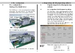
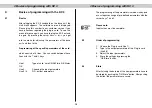
Page 5: ...e card must be activated as below to appear on the list in the Overview of the base unit After reading out the base unit the X QAM twin x card appears on the used slot of the base unit Please note Req...

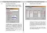
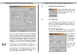
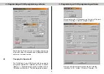
Page 6: ...meters of the chosen QAM bouquet are displayed Those information are TS ID ONID output frequency data ratio and type of modulation 3 3 Programming the card parameters In the overview of the base unit...

Page 7: ...differs in the nonexistent Options of channel A B window 3 4 Testing the input signal quality If you use the button Check signal quality the C N and the Bit error ratio of the input signal of the car...

Page 8: ...arately based on 90 dB V for QAM 64 Examples Channel A Channel B QAM 64 level 90 dB V QAM 128 level 93 dB V Channel A Channel B QAM 64 level 90 dB V QAM 256 level 96 dB V The level will also be adapte...

Page 9: ...ming software 3 Programming with HE programming software 9 With the button Error info you can display the meaning of the error code If a hardware error is displayed please contact our customer service...

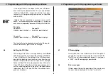
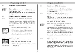
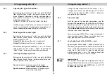
Page 10: ...ese lines with the and keys Line 1 Type of card here X QAM twin A B Status OK Line 2 Choosing the input parameters Line 3 4 RF output parameters The programming of the parameters is made via key pad o...

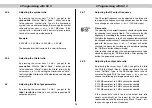
Page 11: ...ut parameters 5 2 1 Adjusting the SAT IF input frequency Line 2 Type in the SAT IF via keypad or change the frequency in 1 MHz steps with the cursor keys or Store the changes with the OK Store button...

Page 12: ...steps Please note The adjusting of the output frequency should always be done by choosing the channel in line 4 This makes sure that the frequency is according to the corresponding channel grid Theref...

Page 13: ...d Spectrum normal output spectrum of the digital signal normal erect sideband Change the output spectrum with cursor keys or Changes have to be saved by pressing the OK Store button By pressing the Me...

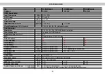
Page 14: ...cos roll off 15 FEC Reed Solomon 204 188 Code Data rate adjust PCR Correction PID Filterung NIT Handling Output symbol rate MBaud dep on input data ratio 3 45 6 9 Bandwidth MHz dep on input data ratio...

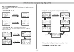
Page 15: ...53 MHz RF Out 121 0 MHz Channel S2 S3 03 Twin6 B OK Input X RF Out 121 0 MHz Channel S2 S3 03 Twin6 B OK SymRate 27 50 MS RF Out 121 0 MHz Channel S2 S3 03 Twin6 B OK Viterbi 3 4 RF Out 121 0 MHz Chan...

Page 16: ...ASTRO Strobel Kommunikationssysteme GmbH Olefant 1 3 D 51427 Bergisch Gladbach Bensberg Tel 49 0 22 04 4 05 0 Fax 49 0 22 04 4 05 10 eMail kontakt astro kom de www astro kom de 82 350 450 03 06 GB...

Reviews: