background image

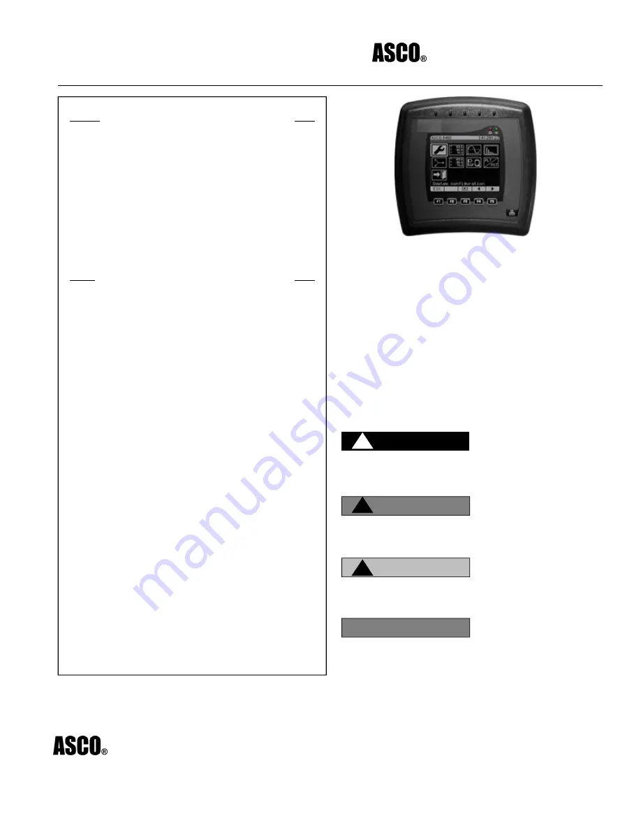
ASCO 5010 Remote Display Unit  


Installation Considerations 

Installation and maintenance of the ASCO 5010 Remote 
Display Unit should only be performed by qualified, 
competent personnel that have appropriate training and 
experience with high voltage and current devices. The meter 
must be installed in accordance with all Local and National 
Electrical Codes and regulations. 

This equipment has no user serviceable parts. 


Important Symbols Used in This Manual


TABLE OF CONTENTS 

Section Page 

 1 

.............. 

Introduction 

............................................................. 

 2 

.............. 

Getting 

Started 

........................................................ 4 


3 .............. Hardware Description ............................................. 6 

 4 

.............. 

Mounting 

................................................................. 

 5 

.............. 

Wiring 

.................................................................... 

10 


6 .............. Navigating through the screens ............................ 12 

 7 

.............. 

Basic 

Configuration 

............................................... 14 


8 .............. Using the ASCO 5010 Remote Display Unit ......... 18 

 9 

.............. 

Monitoring 

............................................................. 

32 

 10 

............. 

Troubleshooting 

.................................................... 

42 

 11 

............. 

Technical 

Definitions 

............................................. 45 

  12 ............. ASCO 5400 Series Website    

                Reference ............................................................. 48 

Figure Page 

Figure 1. 

ASCO 5400 Series Basic Module Unit .................... 2 

Figure 2. 

ASCO 5010 Functional Display Unit ........................ 6 

Figure 3 

External Display Panel (Rear View) ......................... 7 

Figure 4 

ASCO 5010 RDU -Technical Drawing ..................... 7 

Figure 5 

Screw Holes for Affixing RDU to a Panel ................. 9 

Figure 6 

Mounting the Remote Display Device 
to a Panel ................................................................. 9 

Figure 7 

Power Over Ethernet PoE Connection .................. 11 

Figure 8 

Terminals for RS485/422 on the Rear Side 
of the ASCO 5010 RDU ......................................... 11 

Figure 9 

The ASCO 5010 RDU Main Menu ......................... 12 

Figure 10 

The ASCO Welcome Screen followed by the 
Connection Configuration Page ............................. 14 

Figure 11 

The ASCO Search Utility for Finding ASCO Elements 
on the LAN ............................................................. 24 

Figure 12 

The Two Page Configuration Menu ....................... 25 

Figure 13 

The Information Page ............................................ 26 

Figure 14 

Read-only "About" Information .............................. 26 

Figure 15 

Current transformer conductor inserted correctly 
through the ASCO 5400 Series ............................. 28 

Figure 16 

PT/CT Settings- inputting the Primary 
PT Value ................................................................ 28 

Figure 17 

The Main Menu- Default on Power Up .................. 32 

Figure 18 

Large Digits Display- A Typical Page Layout ......... 34 

Figure 19 

The Factors Summary Page: K-factor and  
Crest Factor ........................................................... 36 

Figure 20 

Volt/Amp Summary ................................................ 36 

Figure 21 

The Power Summary Page .................................... 37 

Figure 22 

The THD Summary Page ...................................... 37 

Figure 23 

Waveforms Main Menu .......................................... 38 

Figure 24 

Navigating the Oscilloscope .................................. 39 

Figure 25 

A Harmonic Spectrum Screen ............................... 40 

Figure 26 

The Phasor Display ............................................... 41 

Figure 27 

The Flickering Summary ........................................ 42 

Figure 28 

A Detailed Flicker Summary .................................. 43


POWER


Florham Park, New Jersey  07932-1591   


TECHNOLOGIES

  For sales or service, call: 1 800-800-2726 (ASCO)    www.ascopower.com 


ASCO POWER TECHNOLOGIES CANADA, PO Box 1238, 17 Airport Road 
Brantford, Ontario, Canada N3T 5T3 
 

Series ASCO 5010 Series

IO-70051  Rev. 0  9/12 

5010 Remote 

Display Unit 

1

Operator’s Manual


WARNING is used in this manual to warn of a hazardous 

situation which, if not avoided, could result in death or  

serious injury.

WARNING


CAUTION


CAUTION is used in this manual to warn of a hazardous 

situation which, if not avoided, could result in minor or  

moderate injury. 

NOTICE is used in this manual to address practices not related 

to physical injury. 

NOTICE


DANGER is used in this manual to warn of a hazardous 

situation which, if not avoided, will result in death or  

serious injury. 

DANGER


Summary of Contents for 5010

Page 1: ...g ASCO Elements on the LAN 24 Figure 12 The Two Page Configuration Menu 25 Figure 13 The Information Page 26 Figure 14 Read only About Information 26 Figure 15 Current transformer conductor inserted correctly through the ASCO 5400 Series 28 Figure 16 PT CT Settings inputting the Primary PT Value 28 Figure 17 The Main Menu Default on Power Up 32 Figure 18 Large Digits Display A Typical Page Layout ...

Page 2: ...pecifications PF Power Factor PoE Power over Ethernet PT Potential Transformer RDU Remote Display Unit SCADA Supervisory Control and Data Acquisition SMTP Simple Mail Transfer Protocol SNTP Simple Network Time Protocol SSL Secure Sockets Layer Subnet masking Local Internet subnet masking determined usually by IP admin THD Total Harmonic Distortion Figure 1 The ASCO 5400 Series Basic Module Unit ...

Page 3: ...te Display Installation and Operation Manual This manual instructs the user in the installation configuration and use of the Remote Display to monitor and configure any Power Quality Meter using a direct connection or through a LAN WAN 2 1 Overview The ASCO 5010 LCD Remote Display Unit is an integral part of the ASCO Power Quality Meter system allowing interconnectivity with the ASCO 5400 Series P...

Page 4: ...d configuring tool connecting to each ASCO 5400 Series Power Quality Meter in turn using a CAT 5e 6 network cable with a RJ45 plug or optionally plugging into a network connection and alternately inputting the IP addresses of the different instruments Section 2 Getting Started 2 1 Unpacking The ASCO 5400 Series Power Quality Data Center is shipped with the following Description Quantity 1 ASCO 501...

Page 5: ...fied personnel only To avoid personal injury do not perform any activity other than as contained herein unless you are qualified to do so Before connecting cables to the ASCO 5010 RDU verify that the 48VDC supply is disconnected To prevent shock or fire hazard do not expose the ASCO 5010 RDU to rain or moisture Do not make unauthorized modifications to the ASCO 5010 Always operate the ASCO 5010 RD...

Page 6: ...nterface 5 Function keys and a Network key Figure 2 The ASCO 5010 Remote Display Unit The Status LEDs indicate as follows Green LED External power indication Red LED Failure or indication of incomplete configuration The Header contains the name of the instrument currently connected and the time of day The five Function keys are context sensitive offering dynamic functionality as the unit is used w...

Page 7: ... ASCO 5010 RDU and ASCO 5450 and 5490 LAN2 LCD port will automatically power up connect and open the main menu screen relevant for that specific ASCO 5400 Series PQM currently connected Remote connectivity through an IP network is also applicable but requires configuration as described later in this manual b DC 48V Used for alternative power source for remote connectivity when PoE is not available...

Page 8: ...ASCO 5010 Remote Display Unit 8 3 2 ASCO Technical and Environmental Specifications 3 2 1 Physical Specifications Figure 4 ASCO 5010 RDU Technical Drawing ...

Page 9: ...titude Up to 2000 meters Operating temperature range 4º to 140º F 20º to 60º C Maximum relative humidity 95 Power requirements 10 VA Fuse rating 2 A fuse mounted in line with the AC power supply phase wire Installation Category Class III Pollution Degree Degree 2 Dimensions H W D 197 200 46 mm Panel cutout 135 135 mm Power supply 48 VDC LAN1 PoE in LED backlight 160 128 pixels graphic screen ...

Page 10: ...hind A typical location for mounting the ASCO 5010 RDU is on the front panel of an electrical distribution panel Figure 5 and Figure 6 aid in describing the method of attaching the RDU to a panel A 138 x138 hole is cut out from the panel and the RDU is slid in to place from in front The RDU is then fixed in place using two screws from behind Figure 5 Screw Holes for Affixing RDU to a Panel Figure ...

Page 11: ...the terminal block using a properly sized screw driver The positive wire is to be attached to the terminal marked The negative wire is to be attached to the terminal marked Insert the 48VDC terminal block into the socket marked 48V DC as shown above in Figure 3 The ASCO 5010 Remote Display Unit will operate efficiently using a voltage range from 24 51V DC however only 48V DC may be used through th...

Page 12: ...unication The wires are to be connected to the terminals marked RS485 422 on the ASCO 5010 RDU as shown in Figure 8 and to the marked terminals on the CPU module of the ASCO 5400 Series Power Quality Meter Figure 8 Terminals for RS485 422 on the Rear Side of the ASCO 5010 RDU To enable understanding of the protocol for the purpose of enabling efficient communication basic elements of the protocol ...

Page 13: ...of the display and described textually just above the function key tags Navigation is achieved by pressing the function key under the arrows Entering a chapter is accomplished by pressing the key under the F3 symbol The ASCO 5010 Remote Display Unit displays three distinct types of screens Numeric Display This type of display emulates an electrical panel power meter display comprising three rows o...

Page 14: ...close the current submenu and return to the previous menu Enter Next Select and Close Functions The F3 key is used for ENTER NEXT SELECT or CLOSE All these functions accept the entered information ENTER is also used to open a submenu and to select a menu item At the Installation Wizard NEXT will accept the entered data and move to the next screen SELECT will toggle between the selected inputs and ...

Page 15: ...PQM on the network Password The default password is 123 An administration password is supplied separately by ASCO From this heading the administrator may input his password and freely change parameters on the ASCO 5400 Series Power Quality Meter being configured until he presses the Network key or the keypad is idle for 5 minutes There is no need for any password to change the parameters of the AS...

Page 16: ...rk Parameters No User network parameter Definition 1 DHCP Status toggle DHCP Dynamic Host Configuration Protocol ASCO enables 2 run modes DHCP enable and disable DHCP enabled The ASCO 5400 Series network configuration is automated by the Internet server the ASCO 5400 Series will not keep user input network parameters rather the Internet server configures the network parameters automatically DHCP d...

Page 17: ...to enable connection to one or more ASCO 5400 Series Power Quality Meter via the network Changing the IP address of the ASCO 5010 RDU will disable direct communication via the LAN2 LCD port on the ASCO 5400 Series Power Quality Meter To re enable this direct communication requires changing the IP address of the ASCO 5010 RDU back to the factory default of 192 168 168 100 with subnet mask 255 255 2...

Page 18: ...ing the right arrow Change the address elements using the up and down arrows Lock in the address by pushing the OK button Select Subnet mask and change as necessary using the right up and down arrows Select the Gateway and change as necessary using the right up and down arrows ...

Page 19: ...larity of input waveforms normal reverse Network setup Assign IP address other internet relevant configuration parameters Firmware upgrade These procedures will be described and explained in the following sections 8 1 Connecting for the First Time Connecting to the ASCO 5400 Series Power Quality Meter with the ASCO 5010 Remote Display Unit is accomplished differently depending on the manner in whi...

Page 20: ...Series Power Quality Meter If the ASCO 5010 RDU is to be used as a permanent display for a single ASCO 5400 Series Power Quality Meter the connection is made simply from the ASCO 5010 RDU port to the ASCO 5400 Series LAN2 LCD port using a regular LAN Cat5e 6 cable with RJ45 plugs on both ends No configuring is necessary the communication is plug and play Both the ASCO 5400 Series and the ASCO 5010...

Page 21: ...on of all ASCO 5400 Series Power Quality Meter parameters including the network parameters Navigate to System configuration using right and left and then select F3 Navigate to System information i using right and left and then select F3 Navigate to Network information using the up and down and then select F3 ...

Page 22: ...n the following steps If the DHCP is not disabled the manually input address will not remain since the enabled DHCP will allocate random IP addresses subnet masks and gateways Navigate to the IP address using the up and down and then select F3 Use the right to navigate between the groups and the up and down to increase and decrease the value of the group Press OK F3 when the IP address is complete...

Page 23: ...tor the ASCO 5400 Series Power Quality Meter using the ASCO 5010 RDU across a LAN the IP address for the ASCO 5400 Series PQM must be input to the RDU Since the Network Server randomly allocated addresses to each ASCO 5400 Series PQM the IP address for the ASCO 5400 Series PQM may not be readily available For this purpose ASCO supplies an Automatic Search Utility to find and list all ASCO devices ...

Page 24: ...onfiguration Screen appears again navigate to connect and press Enter F3 The ASCO 5010 RDU and the ASCO 5400 Series PQM are now communicating and configuration and monitoring of the ASCO 5400 Series can continue 8 3 Automatic Search Utility One of the applications of the ASCO 5010 Remote Display Unit is to plug into a network outlet in a LAN and to communicate with any ASCO 5400 Series Power Quali...

Page 25: ...xtend beyond the LAN area The broadcast will extend across most hubs and switches but will not pass gateways routers or firewalls 8 3 1 Using the Search Utility After copying the utility from the CD or downloading from CustomerCare ASCO com double click on the file name or tool icon if the program was equipped with one 1 From the File menu select Refresh List to identify all device IPs on the netw...

Page 26: ...The Two Page Configuration Menu Press on the i to enter the information menu as displayed in Figure 13 The Information page allows unlimited access to read the parameters configured in the previous menu without requiring an administrative password The Information pages are equipped with an Edit button allowing parameter changes to be made from this Information page without having to exit the page ...

Page 27: ...lable for viewing from the Information page are configured in the configuration menu except for one page General Information This page displays the version numbers for the elements of the ASCO 5400 Series Power Quality Meter as shown in Figure 14 Figure 14 Read only About Information ...

Page 28: ...e 123 ABC RST XYZ RYB RWB Reactive behavior Cap Ind Capacitive or Inductive LD LG Lead or Lag Polarity Configuration This page allows for the mathematical software reversal of the current flow through the ASCO 5400 Series Power Quality Meter Both current direction and voltage polarity is a matter of importance in measuring electrical parameters The ASCO 5400 Series Power Quality Meter must be inst...

Page 29: ...ted around the current carrying conductor with the secondary conductors designed to carry no more than 5 amperes in some cases 1 ampere secondary conductors are used A CT designed for a 500A load with a 5A secondary will have a CT ratio of 500 5 The PT or Potential Transformer operates under a parallel methodology a voltage transformer is designed to transform the rated network voltage to a second...

Page 30: ...matically after the last button was pushed Password configuration This is where the access control takes place allowing modification to viewer user and admin passwords Set demand and energy intervals This page allows the user to determine the demand and energy demand intervals Set metering energy time Not currently in use Set time zone The user must input the local offset to UTC Greenwich Mean Tim...

Page 31: ... to enable the PQZip compression software before the instrument begins recording Without enabling PQZip the instrument monitors but does not record To enable PQZip navigate to the PQZip button on the main menu Press the button and arrive at the PQZip main menu Navigate to PQZip enable disable and press on Press the button Press OK to enable disable PQZip ...

Page 32: ... disk space available on the ASCO 5400 Series Power Quality Meter Compression Mode there are two modes of compression Fixed quality the resolution is set according to the accuracy desired this being a function of the measuring accessories If the CTs and PTs are of a specific accuracy it is not necessary to save to the highest resolution Fixed rate in this mode the user sets the amount of memory to...

Page 33: ...ons an explanatory description appears just above the function key tabs For example in Figure 17 the first icon from the upper left is activated and its name System Configuration appears above the function key tabs Table 3 explains each icon and what it accesses The following sections will describe the monitoring screens Figure 17 The Main Menu Default on Power Up Table 3 Main Menu Icon Key Icon M...

Page 34: ...um of 3 phases Active Reactive and Apparent powers 2 Volt Ampere PF Displays an average of the 3 phases for voltage and current and system PF 3 Line to Line voltages Displays phase to phase voltages 4 Line currents Displays phase currents 5 Factors summary Displays crest and K factors 6 Volt Ampere summary Displays a page of voltage and current values including L L and L N voltages Neutral Ground ...

Page 35: ...will toggle the other Large Digit pages producing the Favorite list Figure 18 Large Digits Display A Typical Page Layout Table 4 Displayed Page Elements No Element 1 The Parameter being measured 2 Measured value 3 Units of the measured value 4 Minimum and Maximum values 5 Toggle between empirical and Per Unit Values Table 4 is further explained as follows 1 This field is used in the following page...

Page 36: ...ates the RMS value for each cycle it is not practical to display every value measured The amount of cycles averaged for display is configurable 3 The measured value is displayed along with the element measured for example line to line voltage as opposed to line to neutral voltage or line current 4 Extreme values minimum and maximum values are constantly replaced as new values are generated These v...

Page 37: ...he Summary Pages The last 4 meters listed on the Large Digits meter page are summaries The following figures display the screens in the order of their appearance Figure 19 The Factors Summary Page K factor and Crest Factor Figure 20 Volt Amp Summary ...

Page 38: ...ASCO 5010 Remote Display Unit 38 Figure 21 The Power Summary Page Figure 22 The THD Summary Page ...

Page 39: ...the submenus are Current waveforms L1 Current waveform L2 Current waveform L3 Current waveform L1 L2 L3 Current waveforms Voltage waveforms L1 Voltage waveform L2 Voltage waveform L3 Voltage waveform L1 L2 L3 Voltage waveforms L1 L2 Voltage waveform L2 L3 Voltage waveform L3 L1 Voltage waveform L12 L23 L31 Voltages Voltage Current waveforms L1 voltage current L2 voltage current L3 voltage current ...

Page 40: ...emains in the same position when moving from screen to screen 3 The position in degrees from the origin of the sine cycle 4 Pushing on the magnifying glass key increases the cycles presented in the screen x4 implies 4 cycles presented in the screen 9 3 Harmonics Display The Harmonics Display allows the user to examine the harmonic breakdown of each measured waveform From the Main menu navigate to ...

Page 41: ...y the arrow 3 H5 the 5th Harmonic the amplitude is 3 14 amperes it composes 6 1 of the fundamental current the frequency is 250 Hz and it is in phase at 174º 2 The magnifier expands the harmonics x1 shows the first 31 harmonics x2 shows up to 63 harmonics and x3 shows up to 120 harmonics 3 This arrow points to the harmonic explained in 1 It is manipulated with the right an left arrows F4 and F5 4 ...

Page 42: ...quasi cyclic RMS voltage fluctuation whereby the RMS voltage fluctuates 0 25 4 of nominal voltage at a frequency in the range of 0 4 25 Hz This type of disturbance has been historically defined as causing distress to workers due to flickering lighting The EN50160 defines two types of calculations for arriving at values to be considered unacceptable to human perception of flickering light due to vo...

Page 43: ...9 1 1 portrayed in Figure 18 on page 35 or a summary as described below The parameters displayed in Large Digit Display include the following The ASCO Real Time PST EN50160 Flickering PST EN50160 Flickering PLT Two summaries are also available the Flickering Summary shown in Figure 27 and a detailed summary Figure 27 The Flickering Summary ...

Page 44: ...emote Display Unit 44 The Detailed summary is organized by voltage type as shown below When the voltage type is selected the detailed summary is displayed as shown in Figure 28 Figure 28 A Detailed Flicker Summary ...

Page 45: ...d If problem persists Call ASCO 5 Reset successful Min Max reset Min Max of all V I measurements successfully reset 6 Reset failed Min Max reset Matching error Min Max reset failure Call ASCO 7 Reset successful Demand reset Demand accumulator successfully reset 8 Reset failed Demand reset Matching error Demand reset failure Call ASCO 9 Reset successful Energy reset Energy accumulator successfully ...

Page 46: ... is calculated the same as PST but averaged over 2 10 and 60 seconds This ASCO defined value is valuable in that it enables faster assessment of the flicker ASCO PSST converges to a real value within 3min from a drastic flicker change or immediately for periodic steady state flicker SPLT An ASCO measurement designed to get quicker results regarding Flicker evaluation This measurement reaches a ver...

Page 47: ...eating effects 25 1 2 25 1 2 h h i h i K 15 Active power P The amount of power consumed as usable energy Sometimes referred to as Real power ASCO calculates the Active power accurately by taking all harmonics up to the 40 th into account using the following formula P 2 1 i j i Cos j Ii j Vi Watt Where i is the harmonic an j is the phase 16 Reactive power Q The amount of power consumed as un usable...

Page 48: ...ent frequencies all calculated at multiples of the fundamental h the value of the measurement at the harmonic frequency n the order number of the harmonic 21 Energy Energy is the amount of active power consumed over a set period of time Electrical energy is defined as the amount pf active power consumed over the period of one hour 22 Delivered Energy Imported energy 23 Received Energy Exported ene...

Page 49: ...Configuration Service Power setup 3 Configuration format RST PF Cap Ind Main System configuration System Information Format labels Service Display setup 4 Configuration input voltages currents polarity intended to software resolve inverse polarity connection Main System configuration System Information Voltage Current polarity Service Power setup 5 Configuration set nominal f V I for computation r...

Page 50: ...monics menu Voltages spectrum Monitoring Cycle by cycle harmonics 22 Measurement In harmonics Main Harmonics menu Neutral current Monitoring Cycle by cycle harmonics 23 Measurement Vn harmonics Main Harmonics menu Neutral voltage Monitoring Cycle by cycle harmonics 24 Measurement phasors Main Phasors display Monitoring Phasors Main Energy measurement 25 Energy measurement Delivered Main Energy mea...

Page 51: ...t Real time Pst Power Quality Voltage Flickering column Psst2sec 34 Flickering Pst10min Main Flickering measurement Flickering Pst Power Quality Voltage Flickering column Pst10min 35 Flickering PLT 2H Main Flickering measurement Flickering PLT Power Quality Voltage Flickering column PLT 2H 37 Flickering table Main Flickering measurement Flickering summary Power Quality Voltage Flickering entire ta...

Reviews: