background image


!

10.0 Using the TRINITY GUI

Foreword:

There are two ways to interact with the TRINITY.


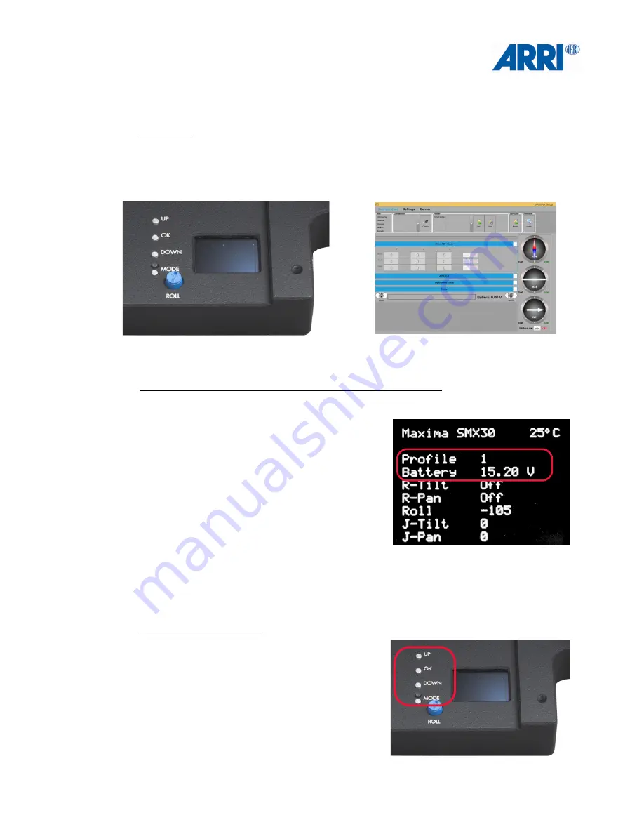
TRINITY user interface  


GUI on Windows 8 or 10 

This is what you will see, when you switch on the TRINITY. 


Most interesting for you will be the highlighted 

information: 

• Selected profile

• Battery charging state

• Value tilt axes

• Value pan axes

• Value tilt axes 
• Value pan axes 
• Value roll axes 


The main push buttons: 

• UP

• OK 
• DOWN

• MODE 

30

Summary of Contents for TRINITY

Page 1: ... USER MANUAL Date 01 March 2017 ARRI CSS camera stabilizer systems 1 ...

Page 2: ... their respective holders and should be treated as such Original version All rights reserved This document is provided under a license agreement containing restrictions on use and disclosure and is also protected by copyright law Due to continued product development this information may change without notice The information and intellectual property contained herein is confidential between ARRI an...

Page 3: ...every country Please check with an ARRI sales representative for availability and additional information Neither ARRI nor its subsidiaries assume any liability for infringement of patents copyrights or other intellectual property rights of third parties by or arising from the use of ARRI products or any other liability arising from the use of such products No license express implied or otherwise i...

Page 4: ... beginners and shall not be used at all without proper training 4 Danger indicates an imminent hazardous situation which if not avoided will result in death or serious injury WARNING indicates a potentially hazardous situation which if not avoided may result in death or serious injury CAUTION indicates a potentially hazardous situation which if not avoided may result in minor or moderate injury NO...

Page 5: ...recautions Functions System Setup Camera Preparation Balancing the System Using the Software GUI Pin Out FCC How to Use This Manual All directions are given from a camera operator s point of view For example camera right side refers to the right side of the camera when standing behind the camera and operating it in a normal fashion The appendix at the back of the manual contains useful reference m...

Page 6: ...V Mount Basic Set K0 0012296 This sets contains TRINITY upgrade Bundle TRINITY Joystick Monitor Mount Transvideo StarliteHD5 ARRI OLED Monitor NOTICE This Monitor is not included in the GPI Pro version TRINTY Battery Mount V Mount or Anton Bauer Gold Mounts ALEXA ALEXA Mini AMIRA Control Cable 6 Pin TRINITY External Power Cable TRINITY PWR LEMO 1B 4pin 1B 4pin TRINITY PWR LEMO 1S 3pin 1B 4pin Or f...

Page 7: ...svideo StarliteHD5 ARRI OLED Monitor ALEXA ALEXA Mini AMIRA Control Cable 6 Pin TRINTY Battery Mount V Mount or Anton Bauer Gold Mounts artemis Docking Bracket 1 8 4 mm Hex Key 5 32 2 mm Hex Key 1 5 mm Hex Key TRINITY External Power Cable Cam Power Cine 12V XLR HiCap Cam Power Cine 12V HiCap ALEXA Cam Power Cine 12V HiCap ALEXA Mini Video Cable HD SDI 4 5 GHz BNC BNC 7 ...

Page 8: ...he Center Post to the HD1 BNC connector at the Top Stage mounted at the bottom of the system This video signal is ideal for Video Transmitters HD2 is indented for the use of the Starlight monitor which is mount to the Gimbal handle EXT The EXT connector is a multi pin accessory connector that carries signals for communication with various accessories 8 ...

Page 9: ...een updated to L Bus Aux Tally Out 12V power to supply accessories Or to connect the artemis external TALLY system Connectors a the Base Front Can Tally Provides a Can Bus or the Tally Trigger Signal CAUTION Do not connect any L Bus Motors or other L Bus products to this connector till the TRINITY had been updated to L Bus Vid Out Video out of the HD2 video signal from the HD2 Video In BNC socket ...

Page 10: ...ble for software interface EXT PWR IN When the TRINITY head is used as a handheld device it can be externally powered through this input CAM PWR ON OFF Power On Off switch for the camera and all other units which are powered by the TRINITY head Connectors at the Base Left side This area is reserved for later customization and future upgrades 10 ...

Page 11: ...u can move the cursor upwards by pressing the DOWN button MODE By pressing MODE you can recall one of your five personal profiles ROLL The blue turn knob ROLL allows you to adjust the horizontal position of the camera NOTICE Make sure the camera is levelled horizontal before you balance the rig Bottom Post Connector There are 3 different Post connectors 1 artemis 3B 2 5 2 artemis 2B 2 5 3 GPI Pro ...

Page 12: ...eset TWO and so on up to preset FIVE Clamp Screw The screw at the side of the bracket is clamping the Joystick housing It is also possible to remove the joystick housing and flip it over to mount the joystick on the underside of the bracket This optional position places the Joystick at the bottom of the bracket as an operator choice Bottom There are two LEMO sockets at the bottom of the Joystick h...

Page 13: ... locker when you mount the extension CAUTION Make sure that the threaded axle is not to deep inside the section which contains the bearing for Yoke axes If the axle is forced into too deep a position the axle will block the Yoke axes 4 2 The TRINITY Battery Hanger The top the TRINITY Battery Hanger is shaped like a camera dovetail plate The shape is the same as the regular artemis camera dovetail ...

Page 14: ...urer Battery Hanger Front Pwr Out This socket will provide 12V High Capacity to power the system reversed through the Top Stage Battery In This two sockets will take the power cables of the Front Battery Mounts Video Pwr This socket provides 12V power to Video Transmitters or other recording accessories Battery Hanger Back Monitor Pwr This socket provides 12V power to any monitor Different monitor...

Page 15: ...lied to ensure that the Pendulum does not swing excessively The Pendulum has a separate side to side adjustment allowing the operator to position the Pendulum always in a line with Center Post This is often used to counter act a top stage that is off center NOTICE Ensure that the Pendulum is centered to the post before you start with the balancing procedure 4 4 The TRINITY Battery Mounts There are...

Page 16: ... facing in the opposite direction from the BNC and power connectors of the monitor Place the rod mounted on the monitor bracket into the bushing of the TRINITY Joystick Monitor Mount The photos show the setup for regular usage NOTICE If you a regular operator you will need to flip the image in the monitor software on both axes You will find the more information in Chapter 8 Left Handed or goofy op...

Page 17: ...ket from the Center Post 2 Use the Post Tool for the following steps Remove the Sled from the Center Post of the artemis system Remove the Top Stage from the Center Post of the artemis system 3 Mount the Top Stage to the lower end of the Center Post NOTICE The Bubble is aligned to the back CAUTION Plug in the main cable connector carefully into the socket of the Top Stage when placing it on the bo...

Page 18: ...extra rod to mount the two batteries onto the rods in the front V shaped as shown NOTICE The clamp lever of the right battery mount has to be close to the knurled fore and aft adjustment knob without touching the knob 11 Connect the batteries to the Battery In Power sockets at both sides of the Battery Hanger 12 Connect the Pwr Out of the Battery Hanger to the Cam Pwr Out of your Top Stage at the ...

Page 19: ...he Post Tool to ensure that the Docking Ring of the TRINITY head is fully tighten DANGER Under no circumstances push fingers or other limbs between the TRINITY Yoke and the inner ring as injuries can result CAUTION Make sure that the yoke of the Docking Bracket is above the longest leg of the stand Securing the stand with sand bags reduces the risk of the tripod falling over Park the TRINITY syste...

Page 20: ...nt Gold Mount K2 0010288 or TRINITY Battery Mount V Mount K2 0010289 In this case the best will be to use four 90 Watt batteries Two in the mounts at the front of the Battery Hanger facing down and two batteries at the back on the pivoting rods one facing down and the other one facing up In this manual we will stay with the more common three battery setup Clearance of the Pendulum After mounting t...

Page 21: ...socket at the bottom of the Joystick housing CAUTION Ensure that all cables are securely routed and cannot be accidentally damaged Connect the 90 elbow 7pin LEMO with 7pin socket at the bottom of the Joystick housing Connect the 7pin LEMO 1B Joystick Main cable with the Joystick socket at the base of the TRINITY Connect the Joystick BNC cable to Video Out NOTICE To get a video signal straight from...

Page 22: ...INITY head as low as possible and the total length of the camera should be as compact as possible NOTICE If the camera length is unnecessarily long the COG of the TRINITY head could be quiet high which will force you to extend the Center Post to compensate for top weight As the Center Post lengthens the more extreme the degree of inertia will be and will reduce the agility of the TRINITY If an ALE...

Page 23: ...of the camera Now place one Focus Motor on each rod Make sure that the gears are facing the front of the lens and the motor housing the camera body If only one Focus Motor is required then still use two rods and place the Focus Motors vertical below the lens This way you can achieve the need for a low COG and symmetry Secure Component Accessory Attachment Keep in mind the TRINITY head is a fully s...

Page 24: ...e to side adjustment Open the clamp of the Quick Lock mounting mechanism and slide the camera inside the ring NOTICE It may be necessary to detach some accessories to mount the camera inside the TRINITY head ring These can be reattached after the camera is mounted NOTICE Make sure that the camera is always level front to back with the COG fully neutral when the camera is horizontally adjusting for...

Page 25: ...are fully tightened That a minimum two batteries are used as counterweight That the Pendulum can rotate freely That the Joystick is connected the right way That all components and accessories are mounted to the camera That the camera is mounted in perfect COG and is neutral and horizontal That the camera dovetail plate is fully tightened That the camera dovetail plate is neutral in the center That...

Page 26: ...tem into a horizontal position Check that the power and video cables have enough clearance to pass the yoke of the TRINITY If needed tape or strap the cable to the camera body NOTICE Turn the Fine Trim adjustment on the post to the middle position Loosen the Gimbal locking clamp and move the Gimbal up and down the post by sliding and rotating the gimbal on the post to reach a neutral horizontal po...

Page 27: ...With the base and the rig in a horizontal position turn the post 5 to the right and let the Rig find its way back to the level horizontal position Do the same starting from the left side Observe any difference in the speed of the correction from the right to the left Using the Left and Right adjustment of the Top Stage and the Left and Right adjustment of the Pendulum adjust the rig until the 5 ro...

Page 28: ...ntal position and redo all steps one more time Take your time and focus on a sensitive final adjustment of the entire system NOTICE The objective in the balancing process is to adjust the rig to allow the operator to move the TRINITY from High Mode to Low Mode in one line While eliminating any side to side rotation while the rig is moving up or down The Pendulum will enable the operator to give th...

Page 29: ...ual Horizon Anamorphic Desqueeze 1 3x Anamorphic Desqueeze 2x Back to main menu Auto REC Reverse mode WARNING This product must be used in a correct grounded electrical environment ground defects can create severe problems to the equipment the picture quality and even cause danger for the user Copyright law and international treaties protect this product its design and its software One or several ...

Page 30: ...face GUI on Windows 8 or 10 This is what you will see when you switch on the TRINITY Most interesting for you will be the highlighted information Selected profile Battery charging state Value tilt axes Value pan axes Value tilt axes Value pan axes Value roll axes The main push buttons UP OK DOWN MODE 30 ...

Page 31: ...h a prime lens and a light matte box Or in other words a camera configuration which is up to 7 Kg 15 4lb NOTICE Follow Mode Means that the camera will follow the movement of the TRINITY operator Fully Stabilized Means the camera will stay in the same position facing the same direction even when the TRINITY is moved in all 3 axes Below you can see the values of the factory presets of the 5 user mod...

Page 32: ... count down After 5 seconds the TRINITY will beep Now switch ON the wireless Remote Control Done 11 0 GUI TRINITY Software All other adjustments have to be done with the GUI which comes with the USB stick The GUI needs a Windows computer or tablet running Windows 8 or 10 or Mac with Parallels NOTICE Make sure you are running the latest GUI The latest version can be downloaded here https www arri c...

Page 33: ...the TRINITY will be uploaded into the TRINITY software 12 0 Adjusting the Motor Power P I D This is what you will see after the profiles have been uploaded from the TRINITY Please focus on the red highlighted values for the moment The power and the torque of the motors have to be adapted to the length and weight of the camera used for setup As stated before the MAXIMA comes with a P I D preset whi...

Page 34: ...nge the number NOTICE Always press WRITE lower right corner after you program the necessary changes NOTICE The last stored user mode will be the first after the TRINITY has been switched on or after changing the battery 34 Light weight Setup Camera up to 7 Kg 15 4lb ROLL P 4 I 0 15 D 4 TILT P 35 I 0 09 D 45 PAN P 35 I 0 09 D 45 Mid weight Setup Camera up to 15 Kg 33lb ROLL P 4 I 0 15 D 4 TILT P 55...

Page 35: ...o increase the P and D values Golden rule number three The D value should always be 10 higher than the P value Golden rule number four If you want to play around with the P and D values just program in steps of 5 up and down Lower value steps than 5 do not make a lot of a difference 12 3 Joystick settings You can set the speed the ramp and the damping as well as the direction of the joystick Speed...

Page 36: ...he MAXIMA has been switched on or after changing the battery 12 4 Damping and Ramp NOTICE Increasing the Deadband value will add more delay before the joystick takes effect NOTICE Increasing the Expo Curve value will add more ramp to the joystick behaviour NOTICE To add a Ramp to the Joystick lower the Expo Curve to 50 and reduce the Speed 30 80 NOTICE If the focal length is over 100mm lower speed...

Page 37: ...ggle the ON OFF switch to single axis For example If you want to switch on the Follow Mode for the Tilt axis then position the switch to ON Or if you want to have the Tilt axis in fully stabilized mode then position the switch to OFF 37 Follow Mode Handheld Easy Rig artemis Arm Vest Fully Stabilized Handheld Hard Mounted Crane Trinity ...

Page 38: ...amount of Ramp after the camera picks up your movement NOTICE A higher value will produce more ramp By changing the speed value you can increase or decrease the speed of the single axis in the follow mode NOTICE Lowering the value will increase the delay and increase the difference between the camera from your movement For example NOTICE These values are suitable for a camera setup with 10 Kg 22lb...

Page 39: ... see if the direction is the right one You can use positive as also negative values NOTICE Press Write 15 0 Troubleshooting NOTICE Before you contact ARRI service please note the serial number of your TRINITY Firmware version and serial number can be found here Press the OK key Press the DOWN till Info Press the OK 39 1 Joystick 2 Remote 3 Calibration 4 Remote Pairing 5 Restore 6 Info 7 Exit ...

Page 40: ...s Press the UP key one time Yes Press the OK key 15 2 Restore Settings If you want to bring all setting to the factory setup follow the steps below Press the OK key Press the DOWN key four times till Restore Press the OK key Settings Press the UP key one time Yes Press the OK key 40 1 Joystick 2 Remote 3 Calibration 4 Remote Pairing 5 Restore 6 Info 7 Exit 1 Joystick 2 Remote 3 Calibration 4 Remot...

Reviews: