Installation
HC-6100/6300 Mounting
The HumidiClean models HC-6100/6300 are designed to be wall mounted. A wall mounting bracket
and lag screws are provided for mounting on 410 mm (16”) centers. The operating weight of the unit is
106 kg (233 lbs). A clearance of 600 mm (23”) on the front and sides of the cabinet is required for
servicing.
1. Position wall mounting bracket level on wall and mark hole pattern. Make sure holes line up with
studs or other sturdy structure.
2. Use 3/8" x 1-1/2" lag screws provided to secure the bracket.
3. Hang the humidifier on the wall mounting bracket. The dry weight of the unit is 70 kg (154 lbs).
HC-6500/6700 Mounting
The HC-6500/6700 HumidiClean is designed to be floor mounted on a level surface. The operating
weight is 230 kg (507 lbs), a clearance of 600 mm (23”) is required for the front and sides.
Water Fill Supply
The humidifier can use any potable or purified water supply. Water pressure must be 25-120 psig.
Water temperature must be less than 60°C (140°F).
1. Install a shut-off valve near the unit.
2. Connect the water supply to the 3/8" compression fitting on the fill water solenoid valve on models
HC-6100/6300. The HC6500/6700 is supplied with a compression filling for 10mm plastic tubing. A
6’ piece of 10mm plastic tubing is included for the larger models. The knock-out for the water
supply tubing is under the fill valve in the bottom wall.
Electrical Service Wiring
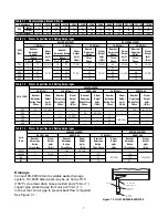
1. Connect main power supply wiring to high voltage terminals in unit. Read breaker size required on
humidifier's nameplate and refer to Table 7-1 and 7-2 for HC-6100/6300 wire (gage) required; Table
7-1, 7-3 and 7-4 for HC-6500/6700. Make sure an interlocking circuit breaker or safety switch (not
furnished) is accessible and within sight of the unit.
2. The humidifier cabinet must be grounded. A ground lug is provided in the cabinet.
3. Use only wire with copper conductors rated at 90°C (194°F) or higher for power supply and
grounding.
6
Summary of Contents for HumidiClean HC-6100 Series
Page 28: ...HC6100 Wye Wiring layout 28...
Page 29: ...HC6100 Delta Wiring layout 29...
Page 30: ...30 HC6100 PAR Single Phase Wiring Layout...
Page 31: ...HC6300 Wye Wiring layout 31...
Page 32: ...HC6300 Delta Wiring layout 32...
Page 33: ...HC6500 Wye Wiring layout 33...
Page 34: ...HC6500 Delta Wiring layout 34...
Page 35: ...35 HC6500 WYE 2 contactors Wiring Layout...
Page 36: ...36 HC6500 Delta 2 contactors Wiring Layout...
Page 37: ...HC6700 Wye Wiring layout 37...


