9. Operate the unit configuration menu “Ionic Time Reset”, to reset the ionic bed life. All the
accumulated ionic bed time has been reset to zero. The unit should now be heard filling.
NOTE: The accumulated ionic bed time can be reset to zero at anytime. However, the unit
should not be reset without first inspecting the ionic beds.
10. After the unit has heated up and started making steam, turn main power off and double check tank
access panel gasket for steam leakage. Hand tighten wing nuts or reposition gasket if necessary.
Cleaning the Water Level Electrodes
1. If there is water in the steam generating tank, operate menu to "MANUAL DRAIN". The drain valve
should energize, and the unit should completely drain.
2. After the tank has drained, turn off the main
power at the disconnect.
3. Unclamp and remove the 5/8" ID Silicone tubing
from the top outlet of the level canister.
4. Disconnect wires #21 (high level probe), #20
(low level probe) and #19 (common probe) from
the probes, noting the probe and wire locations.
Note: Level control float switches are used
for DI, RO, or very pure water. Cleaning
should not typically be required.
5. Unscrew the probes from the level canister
using the hex nut fitting on the probe
(Note: Level canister bushings may be removed with the probes, if necessary).
6. Use a wire brush, wire wheel, or similar means to clean scale deposits off the stainless steel tip of
the probe. Cleaning of the Teflon insulating jacket (white portion) should not be needed.
7. Wipe probes with a clean dry cloth.
8. Inspect the interior of the level canister. If large amounts of scale or debris are present, remove the
canister from the cabinet by removing the two clamping bracket screws and disconnecting the 5/8"
ID Silicone hose at the bottom of the canister. Flush the canister with water to remove debris
and reinstall.
9. Reinstall the probes and probe wires in their proper locations. The high water probe (shortest)
goes in the right hole of the canister. The low water probe (medium length) goes in the left front
hole of the canister. The common probe (longest) goes in the left, rear hole of the canister.
10. Reconnect the 5/8" ID Silicone hose(s).
21
Summary of Contents for HumidiClean HC-6100 Series
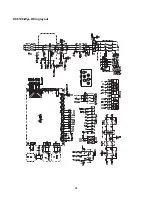
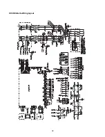
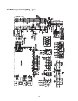
Page 28: ...HC6100 Wye Wiring layout 28...
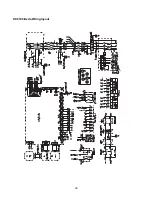
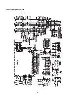
Page 29: ...HC6100 Delta Wiring layout 29...
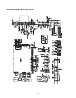
Page 30: ...30 HC6100 PAR Single Phase Wiring Layout...
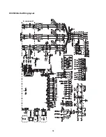
Page 31: ...HC6300 Wye Wiring layout 31...
Page 32: ...HC6300 Delta Wiring layout 32...
Page 33: ...HC6500 Wye Wiring layout 33...
Page 34: ...HC6500 Delta Wiring layout 34...
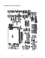
Page 35: ...35 HC6500 WYE 2 contactors Wiring Layout...
Page 36: ...36 HC6500 Delta 2 contactors Wiring Layout...
Page 37: ...HC6700 Wye Wiring layout 37...

