


4. If fuses are OK, check voltage to contactor coil.
(a) If voltage is 24-28VAC at contactor coil, check coil resistance. It should be 8
Ω
with wires
disconnected. If resistance is OK, check voltage drops across the contactor.
(b) If no voltage to contactor coil, check continuity of wires from PC board to contactor. If
continuity is OK, PC board is likely defective.
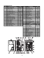
5. Check voltage signal to power module. The voltage across TAB8-1 and TAB8-2 (low voltage signal
to power module) should be 12 Vdc.
(a) If no or low voltage, the PC board is likely defective.
(b) If voltage is OK, but green "SIGNAL" LED on the power module is not on, power module is
defective.
6. If green "LOAD" LED on power module is on, check voltage drops across power module.
Humidifier overfills with water on initial fill.
1. Check electrode canister (float canister for DI units) and level electrodes for debris or scale build
up. Clean as needed. See Page 21 for cleaning procedure for electrodes. On DI Units, the high
water float switch may be defective or "hung up". Check continuity across wires to the switch.
Make sure switch movement is vertical so float lever arm swings freely.
2. The fill valve may be stuck open. Turn off power to the humidifier. If fill valve does not close,
clean or replace valve.
3. If the high water circuit is closed and the fill valve shuts off when the power is turned off, the PC
board is defective.
Humidifier runs continuously, %RH is well over set-point.
1. Verify humidistat signal isn't sending false 100% demand.
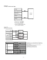
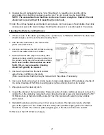
2. Verify humidistat or RH sensor is wired correctly and stat/sensor dip switches (S2 & S3, See
Fig. 10-1 and 11-1) on the PC board are set correctly for the humidistat signal.
3. If humidifier generates steam with the humidistat disconnected.
(a) Check for power at the contactor coil. If 24-28 VAC, PC board is defective.
(b) Check voltage drop across contactor. If voltage drop is low (it should be line voltage),
remove, disassemble and inspect contactor.
(c) Check green "SIGNAL" LED on power module. If it is ON or blinking, PC board is likely
defective.
(d) Check voltage drop across power module. If voltage drop is low (it should be line voltage),
power module triacs may be failed closed. Shut off main power and perform continuity check
across high voltage input and output terminals. Continuity indicates a shorted triac. Note:
Some power modules have two triacs rather than three. Check schematic on power module
to verify.
24
Summary of Contents for HumidiClean HC-6100 Series
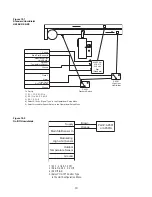
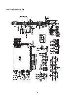
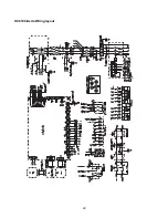
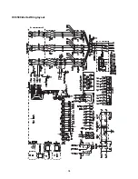
Page 28: ...HC6100 Wye Wiring layout 28...
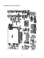
Page 29: ...HC6100 Delta Wiring layout 29...
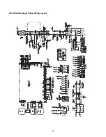
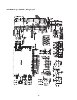
Page 30: ...30 HC6100 PAR Single Phase Wiring Layout...
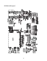
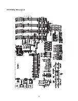
Page 31: ...HC6300 Wye Wiring layout 31...
Page 32: ...HC6300 Delta Wiring layout 32...
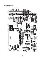
Page 33: ...HC6500 Wye Wiring layout 33...
Page 34: ...HC6500 Delta Wiring layout 34...
Page 35: ...35 HC6500 WYE 2 contactors Wiring Layout...
Page 36: ...36 HC6500 Delta 2 contactors Wiring Layout...
Page 37: ...HC6700 Wye Wiring layout 37...