5)
Restoring the Unit to Operation
a) Turn power on at breaker.
b) Unit should begin to fill. Maximum fill time is approximately 30-45 minutes before
contactor(s) will be closed.
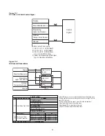
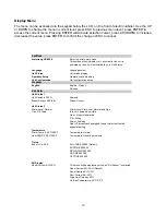
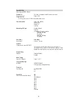
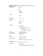
c) If this does not take place, operate the menu, and change the status to "STEAM
GEN."
B.
Modifying the Bed Life Setting
1) Complete the steps for servicing the unit as outlined above.
2) Change the EOL settings to desired value in Unit Status menu.
3) Save settings in menu.
End of Season Drain
If at any time during normal operation there is not a demand for a continuous 72 hour period,
HumidiClean drains the tank and the PC Board initiates a drying cycle by cycling the heating elements
for short intervals in order to dry the ionic beds.
Maintenance
The HumidiClean is designed to minimize maintenance. As stated in the PRINCIPLE OF OPERATION
section, after the HumidiClean has accumulated 90% of the selected Service Life, in hours of heater
on time, the "STATE" LED will flash (blink) in yellow. At this time the ionic beds in the tank should be
replaced. If service is not performed, the unit will continue to operate for the remaining hours before
shutting down completely.
Note:
Service Life can be adjusted based on water quality. If Ionic Beds are relatively free of scale
deposits or scale is forming on tank walls and elements because beds are saturated with scale, please
consult the factory for Service Life adjustment procedures.
Replacing the Ionic Beds
1)
Save the settings, consult the OPERATION SETUP
menu
2) Go to
Steam Gen.
Menu
a) Drain tank by operating menu from "STEAM GEN." to "MANUAL DRAIN" position.
b) Once the tank is drained, shut power off to unit and allow the tank to cool.
c) Remove the cabinet access panels, and slowly open tank access panel.
3) Unsnap ionic beds from support pins and slide them out through the access opening.
19
Summary of Contents for HumidiClean HC-6100 Series
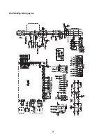
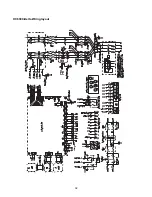
Page 28: ...HC6100 Wye Wiring layout 28...
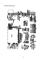
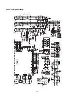
Page 29: ...HC6100 Delta Wiring layout 29...
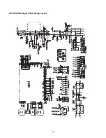
Page 30: ...30 HC6100 PAR Single Phase Wiring Layout...
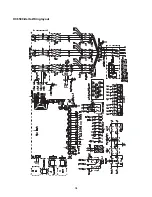
Page 31: ...HC6300 Wye Wiring layout 31...
Page 32: ...HC6300 Delta Wiring layout 32...
Page 33: ...HC6500 Wye Wiring layout 33...
Page 34: ...HC6500 Delta Wiring layout 34...
Page 35: ...35 HC6500 WYE 2 contactors Wiring Layout...
Page 36: ...36 HC6500 Delta 2 contactors Wiring Layout...
Page 37: ...HC6700 Wye Wiring layout 37...


