


20
IT
GB
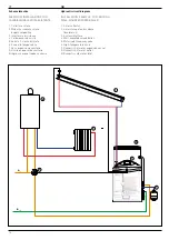
Schema Elettrico
L
N
L
N
L- N L+
A1 A1
AUX1
V1
P1
230V
S1
S2
S3
S4
BUS BUS
B
T B
T
RETE BUS BRIDGENET®
BRIDGENET® BUS NETWORK
ANODO /
ANODE
SONDA RITORNO RISCALDAMENTO
(ove presente)
HEATING RETURN SENSOR
(where present)
SONDA BOLLITORE ALTA
HIGH INDIRECT CYLINDER SENSOR
SONDA BOLLITORE BASSA
LOW INDIRECT CYLINDER SENSOR
SONDA COLLETTORE
COLLECTOR SENSOR
VALVOLA DEVIATRICE
(ove presente)
DIVERTER VALVE
where present)
CIRCOLATORE SOLARE
SOLAR PUMP
TERMOSTATO SICUREZZA
SAFETY THERMOSTAT
(*)
(*)
COLLEGAMENTO
CALDAIE PRE ESISTENTI
CONNECTION OF
EXISTING BOILERS
ALIMENTAZIONE
POWER SUPPLY
230V
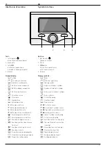
Indicazioni LED / LED signals
LED VERDE (sinistra) / GREEN LED (left)
spento / off
alimentazione elettrica OFF / power supply OFF
fi sso / fi xed
alimentazione elettrica ON / power supply ON
lampeggiante
fl ashing
alimentata ON, scheda in funzione manuale
powered ON, P.C.B. in manual mode
LED VERDE (centrale) / GREEN LED (central)
Luce spenta / Light off
comunicazione Bus BridgeNet® assente o not-OK
BridgeNet® Bus communication absent or not-OK
Luce fi ssa / Fixed light
comunicazione Bus BridgeNet® presente
BridgeNet® Bus communication present
Luce lampeggiante
Flashing light
scansione o inizializzazione della comunicazione Bus BridgeNet®
scanning or initialisation of BridgeNet® Bus communication
LED ROSSO (destra) / RED LED (right)
Luce spenta / Light off
nessun errore di funzionamento / no operation error
Luce fi ssa / Fixed light
presenza di uno o più errori di funzionamento
presence of one or more operation errors
Electrical diagram
Summary of Contents for 3023637
Page 38: ...38 IT GB ...
Page 39: ...39 IT GB ...


