8
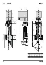
Linearis N+
4.2
Packaging
ARIS actuators are protected by special cardboard packaging at delivery.
4.3
Safe disposal of packaging
Additionally necessary packaging is made by easily separable packaging materials and can be recycled individually:
•
Wood
•
Cardboard
•
Paper
•
Plastics
4.4
Installation and mounting
•
Inspect the actuator for damages prior to installation;
•
the screw-in depth of connecting thread holes must not exceed 9 mm;
•
check leak tightness of cable glands and blank plugs prior to initial operation;
•
tighten the cover screws evenly (max. 1.2 Nm);
•
do not operate before limit switches have been adjusted;
•
protect the actuator against climatic influences (e.g. by a protective cover);
•
do not expose the actuator to hard shocks (e.g. by dropping);
•
do not attach ropes, hooks or the like to the actuator;
•
permanent overload and blocking leads to actuator damages;
•
spark suppressor capacitor can effect the rotation stability of the actuators and may cause damages;
•
use only ARIS original spare parts.
Consider prior to attachment of couplings:
•
Do not turn the thread spindle by force;
•
the attachment to the valve or a solid underground is made by the pre-assembled brackets (bearing blocks).
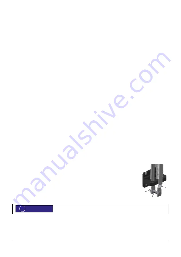
Driver connection
1. The con rods (A) are connected to the valve by a bolt (B).
2. Lubricate moving parts (OKS 416 or similar).
3. Insert the bolt (B) into the bores of the con rods attach the cotter pin (C).
4. Finally bend the cotter pin ends apart.
Installation position
: The actuators can be installed position independendly.
Protection classes IP65 (optional IP 66, IP 67)
For all actuators observe the following advices:
The initial operation of the actuator is only permitted with orderly closed cover and closed cable entries. Use only cable glands
which are appropriate for the respective protection class.
ADVICE
!
A
B
C


