13
Linearis N+
All potis must generally run under a potential divider circuit.
5.3.3
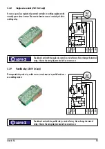
Additional limit switches (Self-adjusting switch cam)
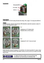
The switch cams can be rotateted by hand an can additionally be fixed with a thread pin,
e.g. at strong vibrations.
1. Approach desired position. Switching position must be approached from the desired rotating
direction.
2. Turn switch cams „1“ to „4“ in rotating direction of the cam shaft E until limit switch „S1“ to „S4“
clicks. Now the thread pin F can be fixed with a hex wrench (enclosed).
3. Check setup by moving the actuator again electrically and adjust if necessary.
5.3.4
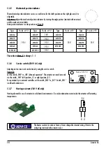
2-wire-current output 4-20 mA
Electrical connection
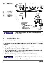
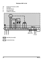
Connect terminal 54 and 55 according to the wiring diagram (see page 10). Use separate (shielded) wire with minimum diameter
of 0.5 mm² and a max. length of 1000 m.
Setup
Operate the current output via buttons „4“ and „20“. Assigning arbitrary positions for 4 mA and 20 mA is possible at any time. The
lower and upper current limit (4/20 mA) is programmed steady.
a) Assignment of end position 4 mA:
•
Approach end position;
•
press button „4“ more than 2 sec.;
•
release button „4“;
•
the end position is programmed and active at once.
b) Assignment of end position 20 mA:
•
Approach end position;
•
press button „20“ more than 2 sec.;
•
release button „20“;
•
the end position is programmed and active at once.
ADVICE
!
18
19
20
U+
U–
U
M
ADVICE
!
F
4
3
1
E
S4
S3
S1
2
S2
R
SR
L
SL


