


26
PMR-Nano
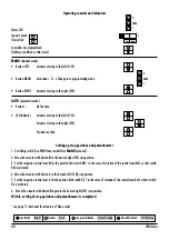
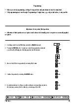
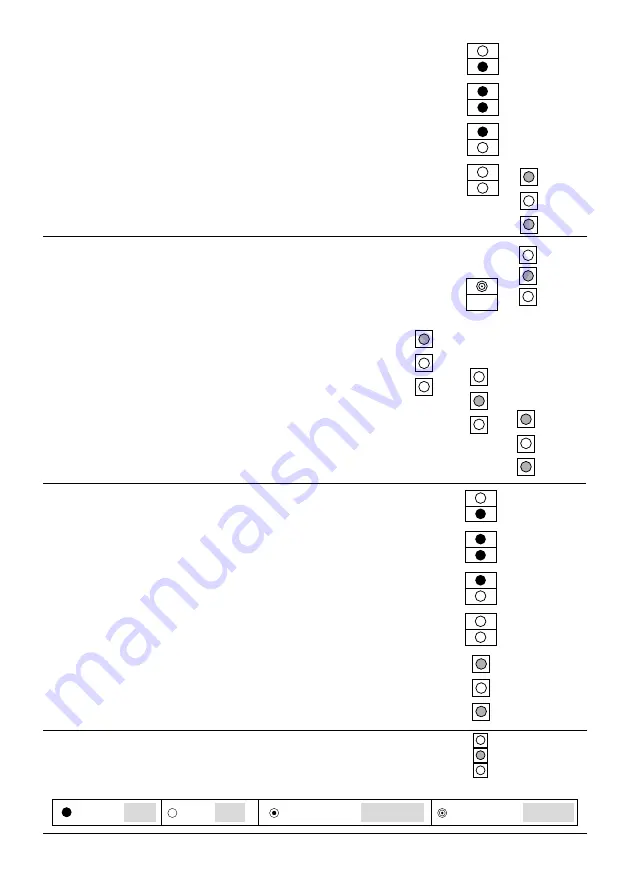
Left set point
0mA
4mA
20mA
externally applied
set point
Change with button
L
/
R
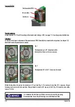
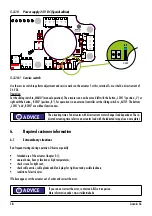
6. Confirm selected set point with the
MENU
button
7. You will see the following short flashing
signal on the LED indicator.
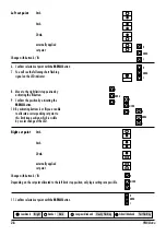
8. Move to the right limit stop position by
activating the
R
button.
9. Confirm the position by activating the
MENU
button.
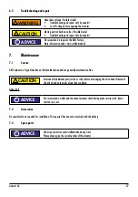
10. By activating buttons
L
or
R
you are able
to allocate a corresponding set point to
this limit stop position, which is visible
by a color change of the LED.
Right set point
0mA
4mA
20mA
externally applied
set point
Change with button
L
/
R
Depending on the set point allocated to the left limit stop position, only logic settings are possible.
11. Confirm selected set point with the
MENU
button
L
MENU
R
L
MENU
R
L
MENU
R
L
MENU
R
L
MENU
R
L
MENU
R
L
MENU
R
Leuchtend Bright Dunkel Dark Langsam blinkend Slowly flashing Schnell blinkend Fast flashing


