Aria-24
ipe
Digital Key Telephone System
Installation Manual
Issue 1.5
Aria Technologies
24
3.2 MBU (Main Board Unit)
Description
The MBU controls the communication between peripheral interfaces, supervises all resources in the
system, controls the gain adjustment of PCM signal, generates system tone and manages call processing
of the system.
The MBU incorporates the main control part that is composed of main microprocessor, RAM and ROM,
the PCM management part, the CO/Extension interface circuits, and the miscellaneous functional circuits.
It provides Loop start CO interface circuits, Digital keyset and SLT interface circuits, DTMF receivers,
Ring Generation Unit, two external relay contacts, one alarm detection circuit, one external PAGE port,
internal/external MOH circuit, the peripheral device decoding circuit, the master clock generation circuit,
the RS232C interface circuit, the system battery backup circuit, as well as system‘s PCM voice processing
circuit that has a flash memory for PCM tone generation and PCM Gain control.
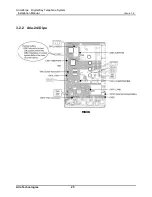
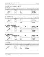
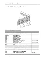
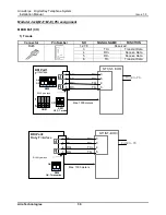
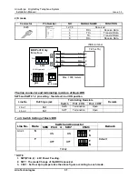
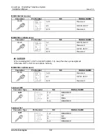
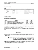
The MBU is installed in the KSU basically. It provides various kinds of connectors and RJ45 modular jacks
for the connection of peripheral boards and miscellaneous functions.
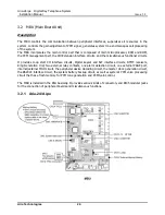
3.2.1 Aria-24/A
ipe
CPCU4

