background image

Aria-24 

ipe

    Digital Key Telephone System 

  Installation Manual 


Issue 1.5 


Aria Technologies 

75 


6.4    Connection of the additional terminals 


6.4.1 Connecting the additional terminal to MBU 


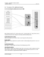
MBU provides connections for 1 external music source, 1 external page port, 2 relay contacts, and an 
alarm/door-bell input monitor through PJ1 audio jack and MJ4 RJ45 Modular Jack. 


External Music Source wiring


MBU accommodates 1 port of external music source through PJ1 (RED) audio Jack. 
 

Relay Contacts


MBU provides 2 relay contacts that are used for loud bell or external paging through pin No. 1-2 & 3-4 of 
MJ4. 
 

External Paging wiring


MBU supports 1 external paging port through Pin No.5-6(paging port) of MJ4. 


Alarm Detection wiring


MBU  provides  an  external  alarm  detection  input,  which  can  be  used  to  notify  to  extensions  when  the 
external switch is closed or opened. This alarm detection input is provided through pin No.7-8 of MJ4. 
Close or open detection is programmable by ADMIN. Programming. 


Summary of Contents for Aria-24/A ipe

Page 1: ...Aria 24 A ipe Aria 24 D ipe Digital Key Telephone System Installation Manual Aria Technologies 895 Wellington Rd Rowville VIC 3178 ABN 22 090 723 925...

Page 2: ...Pty Limited Every effort has been made to ensure that this manual documents the operation of the Aria 24ipe Digital Key Telephone System However due to the on going improvement and update of software...

Page 3: ...Revision History ISSUE DATE Contents of Changes REMARK Field Trial 2004 09 Initial Document 1 0 Jan 2005 CPCU4 1 1 March 2005 Add Aria 24 D ipe 1 2 October 2005 Add Expansion KSU 1 3 April 2006 Add VM...

Page 4: ...the KSU 10 2 1 Before installation 10 2 2 Installation of the KSU 11 2 2 1 Unpacking 11 2 2 2 KSU exterior and dimension 12 2 2 3 KSU with expansion module exterior and dimension 13 2 2 3 Opening and...

Page 5: ...ce Unit 49 3 5 6 MODU MODEM function Unit 50 3 5 7 PLLU Aria 24 A ipe Phase Locked Loop Unit 51 3 5 8 PLLU Aria 24 D ipe Phase Locked Loop Unit 51 Section 4 DECT Installation 52 4 1 Introduction 52 4...

Page 6: ...dditional terminals 75 6 4 1 Connecting the additional terminal to MBU 75 Section 7 Starting the Aria 24ipe System 76 7 1 Before starting the Aria 24ipe System 76 7 2 Basic preprogramming 76 7 2 1 Bef...

Page 7: ...rest on the power cord Do not locate this product where the cord will be abused by people walking on it 9 Do not overload wall outlets and extension cords as this can result in the risk of fire or ele...

Page 8: ...ard do not expose this product to rain or any type of moisture To protect PCB from static electricity discharge body static before touching connectors and or components by touching ground or wearing a...

Page 9: ...e system specifications and capacity Section 2 Installation of the KSU Describes the procedures to install the Aria 24ipe System Detail instructions for planning the installation site Section 3 Instal...

Page 10: ...ommunications Standards GND Ground HDLC High level Data Link Control IEEE Institute of Electrical and Electronics Engineers IP Internet Protocol ISDN Integrated Service Digital Network LDP Keyset seri...

Page 11: ...Board 8 ports SLT Single Line Telephone SMDI Station Message Detailed Information STIB Basic Rate S T Interface TD Transmitted Data TDM Time Division Multiplexing TERM Termination TX Transmitting sig...

Page 12: ...L LC CO OB B B BR RI I M MB BU UB B S ST TI IB B D DK KT TU U D Di ig gi it ta al l P Ph ho on ne e B Bo ox x G G4 4 F FA AX X M MB BU UB B D DT TI IB B R RS S2 23 32 2 M MB BU UB B P PC C A Ad dm mi...

Page 13: ...rogress Tone detection Unit CO Line boards LCOB Loop Start CO Interface 4 ports CPCU4 Caller ID FSK Call Progress Tone detection Unit STIB ISDN Basic Rate S T Interface Board 2 lines 4channels Extensi...

Page 14: ...Contact 1A 30 Volt DC PFT Relay Contact 1A 30 Volt DC Music Source Input 0 dBm 600ohm External Paging Port 0 dBm 600ohm Ring Detect Sensitivity 30Vrms 16 55Hz DTMF Dialing Frequency Deviation Less th...

Page 15: ...Analog CO and or ISDN BRI and or IP Trunk Max direct Station connections 8 MBU 8 DTIB 8 SLIB 8 VOIM Max 24 Max LAN port 1 LANU 1 Max MODEM Channel 1 MODU 1 Attendant Positions 5 System Intercom Links...

Page 16: ...may come into contact with the system 4 Near high frequency generating devices such as sewing machines or electric welders 5 On or near computers telexes or other office equipment as well as microwav...

Page 17: ...System Installation Manual Issue 1 5 Aria Technologies 11 2 2 Installation of the KSU 2 2 1 Unpacking Open the box and check the items below Key service unit Mounting template Tie cable Anchor plug Sc...

Page 18: ...Aria 24 ipe Digital Key Telephone System Installation Manual Issue 1 5 Aria Technologies 12 2 2 2 KSU exterior and dimension...

Page 19: ...System Installation Manual Issue 1 5 Aria Technologies 13 2 2 3 KSU with expansion module exterior and dimension Figure 2 2 3 shows the exterior and dimensions of the KSU Figure 2 2 3 KSU with expans...

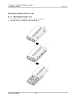
Page 20: ...lephone System Installation Manual Issue 1 5 Aria Technologies 14 2 2 3 Opening and closing the front cover Opening the front cover 1 Turn the screw anticlockwise to loosen 2 Lift the front cover in t...

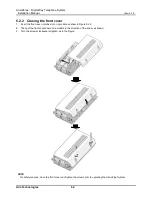
Page 21: ...osing the front cover 1 Insert the front cover into the receptacle of KSU Then put the front cover down on the KSU in the direction of the arrow 2 Turn the screw clockwise to tighten Note For safety r...

Page 22: ...ew Then connect the earthing wire to earth CAUTION 1 For earthing wire Green and yellow insulation is required and the cross sectional area of the conductor must be more than UL 1015 AWG 18 Diameter 1...

Page 23: ...onnector CN19 Aria 24 A ipe The AC input voltage and the fuse rating The Range of Input Voltage Connect to Fuse Ratings 207V AC 253V AC CN19 on the MBU 1A 250V PSU capacity is as followings PSU Type 5...

Page 24: ...Aria 24 ipe Digital Key Telephone System Installation Manual Issue 1 5 Aria Technologies 18 2 Place PSU cover on the PSU as shown below Then turn the screws clockwise to tighten...

Page 25: ...p if the AC power re applied or the battery voltage is too low to maintain proper system operation The system operating time by external batteries depends on several elements as follows battery charge...

Page 26: ...anual Issue 1 5 Aria Technologies 20 2 2 7 Wall mounting 1 Install 3 anchor plugs in the wall with using mounting template Fix the mounting template with 3 screws 2 Hook the KSU onto the screw making...

Page 27: ...Aria 24 ipe Digital Key Telephone System Installation Manual Issue 1 5 Aria Technologies 21 Note Be careful not to drop the KSU...

Page 28: ...Issue 1 5 Aria Technologies 22 2 2 8 Optional mounting Rack 1 Attach the rack bracket to the bottom of the Aria 24ipe system as shown below And to fix the system securely tighten the screw clockwise 2...

Page 29: ...ystem from the static electricity do not touch boards To discharge static touch ground or wear an earthing strap 3 When all boards are unequally inserted the connector pins male pins on MBU can become...

Page 30: ...eous functional circuits It provides Loop start CO interface circuits Digital keyset and SLT interface circuits DTMF receivers Ring Generation Unit two external relay contacts one alarm detection circ...

Page 31: ...Aria 24 ipe Digital Key Telephone System Installation Manual Issue 1 5 Aria Technologies 25 3 2 2 Aria 24 D ipe MBUB...

Page 32: ...allation CN11 LANU installation CN12 CN13 CN14 CPCU4 CN16 JTAG Port for emulator CN17 RS232C interface CN18 System Backup Battery connection See clause 2 2 6 CN19 PSU connection 5V 5V 36V CN20 Externa...

Page 33: ...Extension Connector Socket Pin Number NO SIGNAL NAME RJ45 1 2 3 Reserved 4 5 DKT R DKT T 6 7 8 Reserved MBU MJ2 2 3 4 Extension Connector Socket Pin Number NO SIGNAL NAME RJ45 1 2 DKT R DKT T 3 Reserv...

Page 34: ...hnologies 28 Terminal SLT Connector Type Socket Pin Number NO SIGNAL NAME RJ11 1 2 RESERVED 3 TIP 4 RING 5 6 RESERVED MJ4 Pin assignment MBU Connector Socket Pin Number NO SIGNAL NAME RJ45 1 2 Relay1...

Page 35: ...installation CN16 JTAG Port for emulator CN17 RS 232C interface CN18 System Backup Battery connection See clause 2 2 6 CN19 PSU connection 5V 5V 36V CN20 External GND Terminal See clause 2 2 4 MJ1 4ch...

Page 36: ...8 Reserved 3 TX Transmit Data 4 RX Receive Data 5 RX Receive Data 6 TX Transmit Data NT1 NT BOX 3 6 4 5 RX RX TX TX BRI Port1 TX TX RX RX 3 6 4 T Interface R R SW7 1 2 OFF OFF T mode SW5 1 2 3 4 ON T...

Page 37: ...inating Resistors Remark Switch Pin1 2 ON Pin3 4 OFF Line 1 MJ1 SW5 Termination Open Line 2 MJ1 SW7 Termination Open T or S Switch Setting of Basic BRI Line No Mode Switch and Connector Remark SW5 Pin...

Page 38: ...Reserved 4 5 SLT R SLT T 6 7 8 Reserved CATUION When installing DKT or SLT to Hybrid Port MJ3 1 2 keep the above pin assignment Otherwise DKT or SLT do not operate normally MBUB MJ3 3 4 Extension Con...

Page 39: ...h 3 4 should be placed in the on position and power cycled off and on to initialize the system database to default Once the database has been initialized switch 3 4 should be placed in the OFF positio...

Page 40: ...of Main SYSTEM Power STIB LED indications LED STATUS LINE NO REMARK ON OFF LD7 RED ERROR IDLE 1 BRI GREEN IN USE LD8 RED ERROR IDLE 2 BRI GREEN IN USE CN17 Pin assignment MBU Connector Pin Number NO...

Page 41: ...able to T or S mode 3 3 1 LCOB CID Loop Start CO line Interface Board Description The LCOB provides 4 CO PBX Loop Start CO Line interfaces that support Pulse DTMF signal Each Interface contains ring a...

Page 42: ...n Remark CN1 CN2 and CN3 CPCU4 connection See clause 3 3 1 3 MJ1 2 ports RJ45 type CO line connection 3 3 1 3 CPCU4 FSK CID PR and CPT detection Unit Description Provides four call progress tone detec...

Page 43: ...1st BRI port can be operated to T mode and S mode and the 2nd port can be set to only T mode STIB should be installed on the LCOB STIB connector S T Interface selection on BRI1 Ch1 The default is T I...

Page 44: ...X Transmit Data 4 RX Receive Data 5 RX Receive Data 6 TX Transmit Data NT1 NT BOX 3 6 4 5 RX RX TX TX STIB Port1 TX TX RX RX 3 6 4 T interface R R SW2 1 2 OFF OFF T mode SW4 1 2 3 4 ON T S CN1 5 RJ45...

Page 45: ...ED1 RED ERROR IDLE 1 STIB GREEN IN USE LED2 RED ERROR IDLE 2 STIB GREEN IN USE The line connector and terminating resistors SW 1and SW4 s 1 2 pin setting the default is all ON position Line No RJ45 ty...

Page 46: ...T or S Switch Setting Line No Mode Switch and Connector Remark SW4 Pin 3 4 SW2 CN1 Line 1 S ON ON T OFF OFF Default Line 2 T Only NOTE 4 SW4 Pin3 4 40V Power Feeding 5 SW2 The mode Change of the BRI t...

Page 47: ...line telephone Interface 36V 8 ports 3 4 1 DTIB4 Digital Terminal Interface Board Description The DTIB4 provides Digital Keyset interface of 4 ports It also provides 2 wire connection to Digital Keyse...

Page 48: ...2 wire connection to Digital Keysets It has module connectors MJ1 and MJ2 which is used to connect Digital Keyset lines to the DTIB8 DTIB8 can be installed the SLIB DTIB connector Pin assignment DTIB...

Page 49: ...DTMF receivers The connection between the SLIB4 and Single Line Telephone is performed through RJ45 Modular Jack MJ3 SLIB4 can be installed the SLIB DTIB connector Pin assignment SLIB4 Connector Sock...

Page 50: ...TMF receivers The connection between the SLIB8 and Single Line Telephone is performed through RJ45 Modular Jacks MJ2 MJ3 SLIB8 can be installed the SLIB DTIB connector Pin assignment SLIB8 Connector S...

Page 51: ...Item Record Play MOH Channel 2 channels 1 channel Max record time System time stamp User record time 100 Min 28 Min 72 Min 60 Sec Max Number of User voice message 400 EA Note User Greeting is not lost...

Page 52: ...Item Record Play MOH Channel 2 channels Max record time System time stamp User record time 28 Min 28 Min Not Possible Note User Greeting is not lost by system power off or reset because of this messa...

Page 53: ...ACD UCD announcement and User Greeting ITEM RECORD PLAY MOH Channel 3 channels 1 channel Max record time System time stamp User record time 200 Min 28 Min 172 Min 60 Sec NOTE VMIBE is supported from s...

Page 54: ...ption The AAFBE can be installed on the VMIB AAFB connector and provides system announcement and ACD UCD announcement ITEM RECORD PLAY MOH Channel 3 channels Max record time System time stamp User rec...

Page 55: ...should be installed on the LANU connector Pin assignment LANU Connector Socket Pin Number NO SIGNAL NAME FUNCTION RJ45 4 5 7 8 RESERVED 1 TX Transmit Data 2 TX Transmit Data 3 RX Receive Data 6 RX Rec...

Page 56: ...sue 1 5 Aria Technologies 50 3 5 6 MODU MODEM function Unit Description MODU provides analog modem connection Supports Bell ITU T V 34 V 32BIS V 90 Protocol 300bps up to 33Kbps speed rate Automatic ra...

Page 57: ...ation circuits When STIB is installed on the MBU PLLU must be installed for clock synchronization PLLU should be installed on the PLLU connectors The LED function No Function Remark LED1 The status of...

Page 58: ...registered in accordance with the GDC 345H 400H Wireless Terminal User Guide The WTIB WDIB provides the standard interface between the ipLDK 20 and DECT network The WTIB WDIB provides three or four wi...

Page 59: ...900MHz The following table shows the capacity of WTIB WDIB WTIB WDIB Capacity Items WTIB WDIB Maximum Cell Number Number of Base Stations 4 Voice channels Cell 4 Maximum registered terminals 16 Max Si...

Page 60: ...ts below Figure 4 2 1 WTIB Wireless Terminal Interface Board NOTE 1 The WTIB should only be installed when power to the system is Off installation with power On will cause damage to the system and or...

Page 61: ...Default Switch 3 1 Operation TBR6 mode Normal service mode OFF Switch 3 2 Echo canceller Control Echo canceller on Echo canceller off ON Switch 3 3 Reserved Reserved ON Switch 3 4 Base reset mode All...

Page 62: ...nterrupt operation LED 3 Voice channel active LED 4 Echo canceller enable WDIB Connector 1 Modular Connector Number Cell Number WTI WTI1 Cell 1 WTI2 Cell 2 WTI3 Cell 3 WTI4 Cell 4 WDIB Connector 2 Mod...

Page 63: ...ns insert the screws and tighten leaving about 3mm gap between the wall and screw head Mount the base station on the screws and tighten the screws securely Figure 4 3 1 The back side of the GDC 400B B...

Page 64: ...B Before mounting base station permanently you should determine a suitable location providing the best coverage Use the last sheet of this manual for mounting template to drill pilot holes in the wall...

Page 65: ...ation of the Ferrite core and wiring Ferrite core is provided in the package of Base station for EMI Ferrite core should be installed when WTIB WDIB is installed in the key telephone system One Ferrit...

Page 66: ...LIM and DTIM MODULE PORT CONNECTOR TYPE DESCRIPTION CABLE REMARK VOIM 1 port RJ45 Voice Over Internet Protocol interface 4 wire SLIM 4 ports RJ45 Single Line Telephone interface 8SLTs 2 wire 2SLTs por...

Page 67: ...allation Manual Issue 1 5 Aria Technologies 61 Opening and closing the front cover 5 2 1 Opening the front cover 1 Turn the screw counter clockwise to loosen as shown in Figure 5 2 1 2 Lift the front...

Page 68: ...Insert the front cover into the slot on a module as show in Figure 5 2 2 2 Then put the front cover down on a module in the direction of the arrow as shown 3 Turn the screws clockwise to tighten as i...

Page 69: ...ion Manual Issue 1 5 Aria Technologies 63 5 3 Mounting Expansion Module 5 3 1 Connecting Expansion Module to KSU 1 Insert the expansion module into the slot of basic KSU as show in Figure 5 3 1 2 Turn...

Page 70: ...64 5 3 2 Wall mounting The KSU with an expansion module is mounted on the wall in the same way with basic KSU and an expansion module itself is not mounted on the wall as shown in Figure 4 3 2 FIGURE...

Page 71: ...ogies 65 5 3 3 Rack Mounting 1 Attach the rack bracket to the bottom of an expansion module as shown in Figure 5 3 3 1 Figure 5 3 3 1 Rack Bracket 2 Attach it to a module securely by tightening the sc...

Page 72: ...e bracket with the 4 screws provided Figure 5 3 3 3 4 Connect an expansion module to basic KSU with the flat cable packed in the bracket package IP LDK 20 ERB Expansion Rack mounting Bracket as shown...

Page 73: ...ions and VoIP features with optional VoIP daughter board The VOIM has the capacity of maximum 8 channels with one VOIU and VOIU provides 4 VoIP channels ITEM Specification LAN Interface 10 100 Base T...

Page 74: ...iscellaneous functions refer to the following Table Various switches and connectors functions Switch Connector Functions Remark SW1 Watch dog reset enable Default Off SW2 VOIB Reset Switch for CPU S32...

Page 75: ...y OFF Idle LD7 Channel4 Seize indication LED ON Busy OFF Idle LD8 Channel3 Seize indication LED ON Busy OFF Idle LD9 Channel2 Seize indication LED ON Busy OFF Idle LD10 Channel1 Seize indication LED O...

Page 76: ...sue 1 5 Aria Technologies 70 5 4 2 VOIU Voice over Internet Protocol Interface Unit Description The VOIU can be installed on the VOIB through CN2 and CN3 and provides the Ethernet interface for S W ap...

Page 77: ...the Terminal Various types of digital terminals are used with Aria 24ipe MBU DTIB4 DTIB8 as below Model Description LDP 7008D 8 Flexible Button Display LDP 7016D 16 Flexible Button Display LDP 7024D...

Page 78: ...Aria 24 ipe Digital Key Telephone System Installation Manual Issue 1 5 Aria Technologies 72 6 2 Maximum cabling distance of the Terminal...

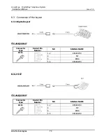
Page 79: ...ogies 73 6 3 Connection of the keyset 6 3 1 Digital keyset Pin assignment Connector Type Socket Pin Number NO SIGNAL NAME RJ11 1 2 RESERVED 3 TIP 4 RING 5 6 RESERVED 6 3 2 SLT Pin assignment Connector...

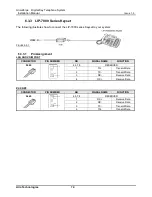
Page 80: ...your system FIGURE 6 3 1 LIP 7000 SERIES KEYSET CONNECTION 6 3 3 1 Pin Assignment LAN AND VOIM PORT CONNECTOR PIN NUMBER NO SIGNAL NAME FUNCTION RJ45 4 5 7 8 RESERVED 1 TX Transmit Data 2 TX Transmit...

Page 81: ...iring MBU accommodates 1 port of external music source through PJ1 RED audio Jack Relay Contacts MBU provides 2 relay contacts that are used for loud bell or external paging through pin No 1 2 3 4 of...

Page 82: ...ld be set ON 3 Plug the AC power cord into the Aria 24ipe System and AC outlet 4 Program the country code 5 Make a reset of the Aria 24ipe System 6 Set the 4th pole of SW3 on the MBU MBUB to OFF when...

Page 83: ...e assigned PGM 113 FLEX 1 but only 1 DKTU can be active in programming mode at any one time Upon entering the program mode the station 10 cannot operate as a normal telephone but as a programming inst...

Page 84: ...ere are many kinds of DKTU connecting to the Aria 24ipe system This model of LDP 7024D is a sample that just shows each button The detailed information about DKTU and other keyset is described in DKTU...

Page 85: ...the TRANS PGM button can go the previous status When the TRANS PGM button is pressed the LCD will display NOTE 1 To return the parent state while ADMIN programming press the CONF button Pressing the...

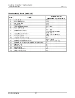
Page 86: ...ite Name 100 Enter Site Name 13 1 10 A 21 B 22 C 23 2 20 D 31 E 32 F 33 3 30 13 1 10 A 21 B 22 C 23 2 20 D 31 E 32 F 33 3 30 G 41 H 42 I 43 4 40 J 51 K 52 L 53 5 50 M 61 N 62 O 63 6 60 G 41 H 42 I 43...

Page 87: ...233 Greece 30 Guam 671 Guatemala 502 Guyana 592 Haiti 509 Honduras 504 Hong Kong 852 India 91 Indonesia 62 Iran 98 Iraq 964 Ireland 353 Israel 972 Italy 39 Japan 81 Jordan 962 Kenya 254 Korea 82 Kuwai...

Page 88: ...mber Set Type 1 10 37 Yes As the basic type the 1st digit of station number should be 1 4 2 Number Set Type 2 10 37 No The station number can be changed within 79 3 Number Set Type 3 10 37 No 4 Number...

Page 89: ...E Etc CODE DTIB4 DTIB8 SLIB4 SLIB8 WTIB WDIB 11 12 13 14 15 LCOB2 LCOB LCOB4 CBIB VOIB 33 34 54 41 STIB STIB1 52 53 VMIB AAFB VMIBE AAFBE 61 62 64 65 Board type of basic MBUB Slot 1 Slot5 and VMIB slo...

Page 90: ...05 CO slot on MBUB 06 Optional CO slot 09 VOIM slot 5 Press HOLD SAVE to accept change STA Board 1 Press Trans PGM 103 2 Press FLEX2 3 Enter logical slot number STA board slot 4 01 Hybrid slot on MBUB...

Page 91: ...LCD to range end All LEDs of BTNs are off Press one of FLEX 1 4 Each FLEX 1 4 is assigned to station number 1 4 on the current LCD then LED of pressed Flexible button is steady on Dial new station num...

Page 92: ...3 Internal All Call Page 543 4 Meet Me Page 544 5 External Page Zone 545 6 All Call Page Internal External 549 7 SMDR Account Code 550 8 Flash Command to CO Line 551 9 Last Number Redial LNR 552 10 D...

Page 93: ...r 569 5 Call Park Location Range 601 608 6 Direct Call Pick Up 7 7 Access CO Line Group 801 808 8 CO Group Number 8 Access Individual CO Line 8801 8812 88 CO Line Number 9 Tie Routing Access 8901 10 A...

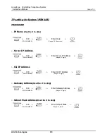
Page 94: ...108 Enter Code Server IP Address 108 Enter Server IP Address CLI IP Address 108 Enter CLI IP Address Gateway Address Use the to skip 108 Enter Gateway Address Subnet Mask Address Use the to skip 108 E...

Page 95: ...urpose is the default position Bad board connection System database broken DKTU does not operate Bad extension circuit Exchange the abnormal board for normal one Bad connection between the MBU DTIB an...

Page 96: ...f switch Check the switch of term and So To position Network problem Check the network side Noise on External Paging port Induced noise on the wire between the system and the amplifier Use a shield ca...

Reviews: