60
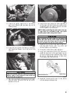
3. Compare the resistance reading to the Voltage/
Resistance Chart - Coolant Temperature in this
manual. If resistance is not within the specifica-
tion, replace the sensor.
NOTE: A coolant temperature sensor voltage test
can be made using the EFI Analyzer.
NOTE: The coolant temperature sensor is located
at the lower half of the crankcase. To remove the
sensor, the engine must be removed.
Testing Air Temperature Sensor
Resistance
NOTE: The component temperature must be
known before conducting this test. Allow the
engine to reach room temperature.
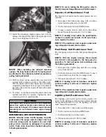
1. Disconnect the wiring harness from the air temper-
ature sensor.
AO135D
2. Set the meter selector in the OHMS position and
test the two leads located in the sensor connector.
Compare with the Voltage/Resistance Chart - Air
Temperature in this manual.
NOTE: The air temperature sensor utilizes a
thermistor, which is very sensitive to temperature
changes. Resistance will change as temperature
varies.
Removing Air Temperature Sensor
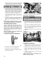
1. Disconnect the wiring harness from the air temper-
ature sensor.
2. Using a standard screwdriver, pry the sensor end
to end to remove it from the air silencer. Account
for two push pins.
Installing Air Temperature Sensor
1. Place the sensor into position in the air silencer
and secure with push pins.
2. Connect the wiring harness to the air temperature
sensor. Secure the sensor leads with cable ties so
they do not rub on any other components.
Removing Throttle Body
NOTE: The expansion chamber and air silencer
must be removed for this procedure.
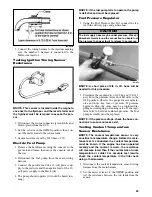
1. Disconnect the wiring harness from each injector
and from the throttle position sensor connector.
2. Remove the coolant hoses from the throttle body
assembly and plug them to prevent leakage.
3. Remove the fuel supply hose from the fuel rail.
4. Loosen the flange clamps.
5. Slide the throttle body assembly out of the flanges;
then loosen the jam nut securing the throttle cable
and remove.
6. Remove the oil pump cable from the oil pump.
7. Remove the throttle body assembly.
Installing Throttle Body
1. Attach the throttle cable to the throttle body.
Secure with jam nut.
2. Place the throttle body assembly into position.
Make sure the flanges and boots are positioned
properly. Secure with flange clamps.
3. Connect the oil pump cable to the oil pump and
secure with the jam nuts.
NOTE: The coolant hoses must be connected
first; then the throttle body assembly must be
installed.
4. Secure the coolant hoses to throttle body assem-
bly.
5. Connect the fuel supply hose to the fuel rail.
729-325A
CAUTION
Since the fuel supply hose may be under pressure,
remove it slowly to release the pressure. Place an
absorbent towel around the connection to absorb fuel.
CAUTION
These hoses must be connected to the correct fittings.
Summary of Contents for 500 Sno Pro
Page 1: ...TM SHARE OUR PASSION Operator s Performance Manual Performance Manual 500 Sno Pro...
Page 2: ......
Page 6: ...NOTES...
Page 22: ...16 NOTES...
Page 68: ...62 NOTES...
Page 92: ...86 NOTES...
Page 93: ...87 NOTES...
Page 94: ...88 NOTES...
Page 95: ...Printed in U S A Trademarks of Arctic Cat Inc Thief River Falls MN 56701 p n 2258 721...


