181
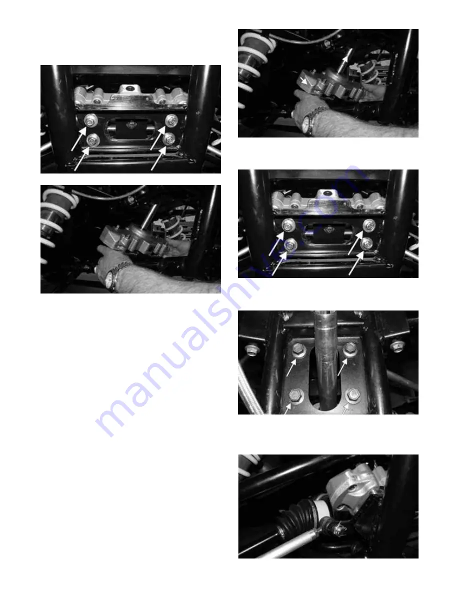
5. Remove four cap screws securing the rack and pinion
assembly to the frame; then rotate the rack and pinion
assembly to the rear and out of the frame from either
side.
WC260A
WC279
INSPECTING
1. Inspect the input shaft splines for excessive wear or
signs of misalignment.
2. Inspect the slide mechanism for pitting, excessive
wear, or worn bushings.
3. Rotate the input shaft from center to full left and right
checking for any binding or catching.
4. Check for loose cap screws on rack and pinion housing.
5. Check for seal damage or lubricant leaks.
NOTE: The steering assembly (rack and pinion) is
not repairable and must be replaced as an assembly;
however, the tie rods and boots are replaceable.
INSTALLING
1. Place the rack and pinion assembly into the frame and
guide the steering input shaft up through the shaft
opening; then rotate the assembly forward and into
position on the front mounting bracket.
WC279A
2. Secure the bracket to the frame with four cap screws
and tighten to 20 ft-lb.
WC260A
3. Install the upper mounting bracket in the frame and secure
with new “patch-lock” cap screws. Tighten to 20 ft-lb.
WC278A
4. Connect the tie rods to the steering rack and secure
with the nuts (threads coated with red Loctite #271).
Tighten to 55 ft-lb and install new cotter pins.
WC257


