


121
The control voltage value is stable for a long time, so we don’
t suggest our
customers adjust it.
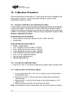
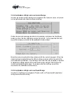
10.4 Adjust the Amplifier Inverter DC Bus Voltage
1. Connect the DVM to the TP6(+) and TP7(-) points on the DDC61000
board and set to DC volts.
2. Power ON the instrument without load.
3. Adjust the VR1 on the DDC61000 board so that DVM measures “+320V”
volts +/- 0.3V
4. Power the instrument OFF then disconnect the DVM.
Note:
We will adjust the DC Bus voltage before leaving our factory. The DC Bus
voltage value is stable for a long time, so we don’
t suggest our customers adjust
it.
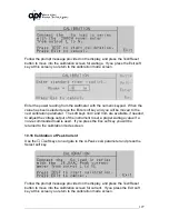
10.5 Clear the Output High Frequency Noise
1. Connect the output of the instrument to the Oscilloscope.
2. Adjust the Oscilloscope to approximately 200mV/10us. This will allow
viewing of the high frequency noise.
3. Set the output voltage to “0” volts in the low voltage range and activate the
output of the instrument.
4. Adjust Inductor L4 on the OPT61000 Output board so that the output high
frequency waveform is set to minimum and displayed on the Oscilloscope
is <= 3000mV P-P.
5. Disconnect the Oscilloscope and power the instrument OFF.
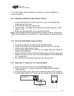
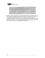
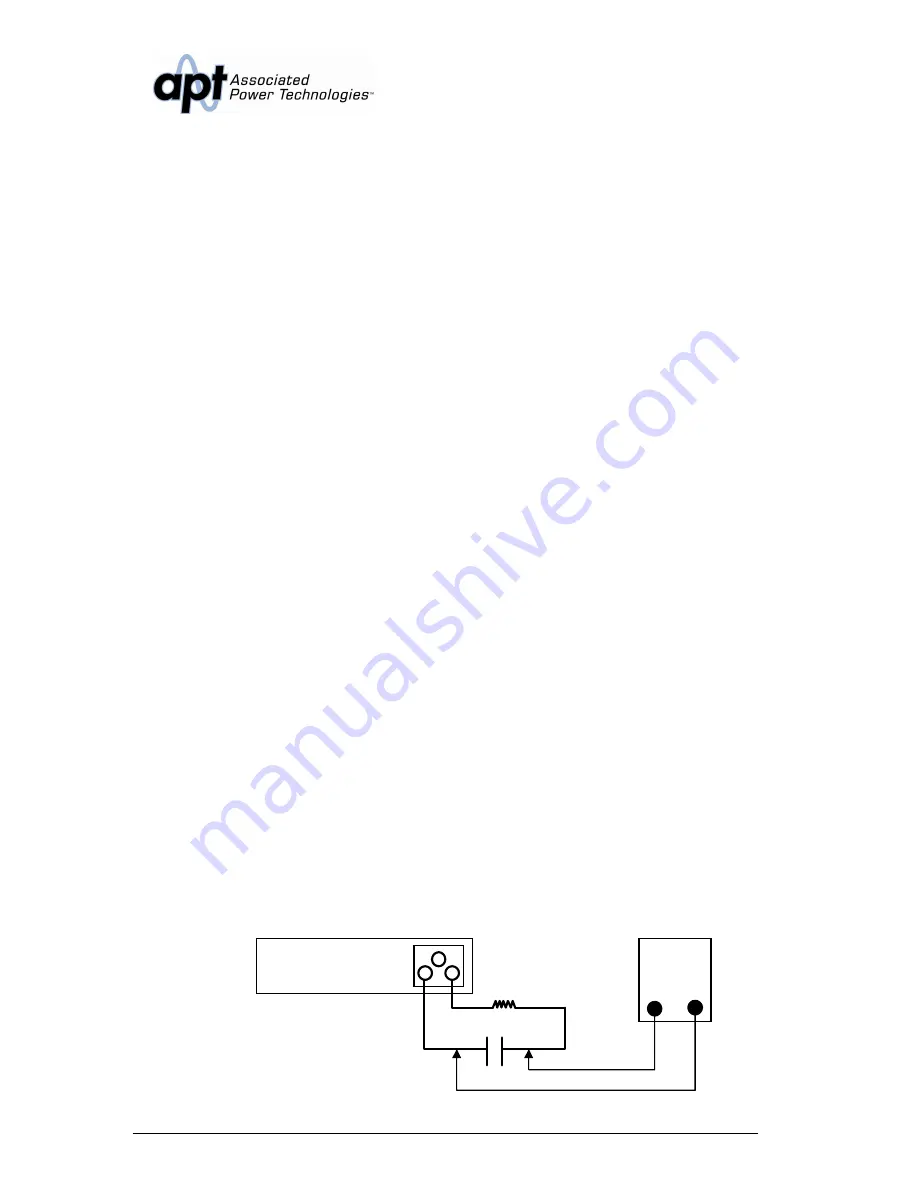
10.6 Adjust the “0” Volts and “110” Volts DC Offset
1. Use the jumper to short the JP1 on the ANG66000 board.
2. Press the “0” and “7” number keys while simultaneously powering the
instrument ON.
3. Connect the DVM to the output of the instrument and set to DC millivolts.
4. Set the output voltage to “0” volts in the low voltage range and activate the
instrument
R475K
C 10uF
DVM
Summary of Contents for 310XAC
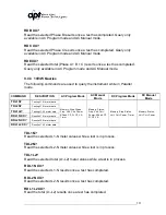
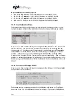
Page 13: ...13 320XAC 340XAC...
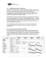
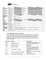
Page 116: ...116 1 Test Complete OK WAI Wait for next command...


