

120
10. Calibration Procedure
All Associated Power Technologies, Inc. instruments have been calibrated at the
factory prior to delivery. The recommended calibration cycle for all APT
instruments is every 12 months.
10.1 Hardware Verification and Calibration Procedure
This instruction sheet covers the hardware calibration procedure for the 300XAC
series power supply. This procedure should be used before standard software
calibration if hardware verification procedure fails. All Tests should be performed
at 60Hz. If the hardware verification does not require adjustment proceed to
10.2
Software Calibration Procedure
.
Required Measurement Standard
•
DVM capable of measuring millivolts DC and 115VAC, 400VDC
•
Oscilloscope
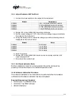
Required Measurement Equipment
•
475k , ¼ watt resistor
•
11 , 1125Watt (minimum) resistor (310XAC)
•
5.5 , 2250Watt (minimum) resistor (320XAC)
•
2.75 , 4500Watt (minimum) resistor (340XAC)
•
1.8 , 6750Watt (minimum) resistor (360XAC)
•
10uF, 110V non-polarized capacitor
•
Potentiometer adjustment tool
•
Inductor adjustment tool
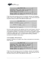
10.2 Activate Non-Calibration Mode
•
Press the “0”
and “7”
keys while simultaneously powering the instrument ON.
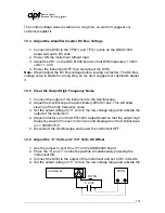
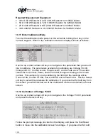
10.3 Adjust Control Circuit Power Voltage
1. Connect the DVM to the “+15V” and “G” points on the FLY61000 board
and set to DC volts.
2. Press the “0” and “7” number keys while simultaneously powering the
instrument ON.
3. Adjust the VR1 on the FLY61000 board so that DVM measures “+15V”
volts +/- 0.1V.
4. Power the instrument OFF then disconnect the DVM.
Note:
APT adjusts the control voltage before the instrument leavees our factory.
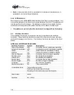
Summary of Contents for 310XAC
Page 13: ...13 320XAC 340XAC...
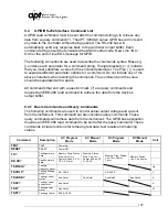
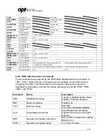
Page 116: ...116 1 Test Complete OK WAI Wait for next command...


