-
22
-
English
Installation
AP030026
C17
C15
4.4
POSITIONING THE FRONT MOUNTING
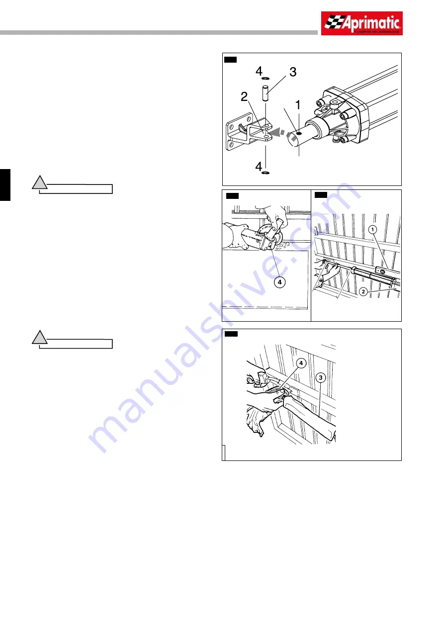
Smear the hole of the operator rod with grease (
C14
pos.
1
).
Position the end of the rod into the front mounting (
C14
pos.
2
),
then
fi
t the locking pin (
C14
pos.
3
) without tightening the snap
rings (
C14
pos. 4).
If it has been decided to use the maximum useful length of the rod
(distance A+B = useful piston stroke length), proceed as follows:
•
Position the key (
see paragraph 6
) onto the unlock screw and
rotate counter-clockwise to hand-unlock the operator.
•
Slowly extend the rod to end stroke.
•
Withdraw the rod of 5 mm.
•
Protect the rod (
C17
pos.
3
).
•
Perfectly clean the welding zone for the front mounting with a
suitable tool (
C15
pos.
4
); be especially sure to remove any traces
of paint or zinc coating.
Warning
!
• Check the strength of the mounting zone; if necessary, fi t
a strengthening plate of the correct size; the strengthening
plate is especially important with gate leaves made from
thin sheet steel.
• When cleaning the mounting zone for the operator front
mounting, remove the operator and protect it from fl ying
sparks.
Rest a water level (
C16
pos.
1
) on the operator body (
C16
pos.
2
)
and level the operator.
Weld the front mounting of the rod to the gate leaf with two weld-
points, protecting the rod from weld residues with a clean cloth
(
C17
pos.
4
).
Withdraw the rod from the front mounting and remove the operator
itself from the temporary mountings to complete the welding. Protect
the pin (using a clean cloth or adhesive tape) from weld residues,
then clean off the residues with a wire brush.
After cooling, apply a coat of rustproof paint to the welded zone.
Warning
!
• While welding the points on the front mounting with the
electrode, always cover the rod with a clean cloth; a splinter of
molten metal can cause irreparable damage to the machined
surface and make the operator unusable.
• During welding, the operator must be disconnected from
the electricity supply.
C14
300 mm
C16


