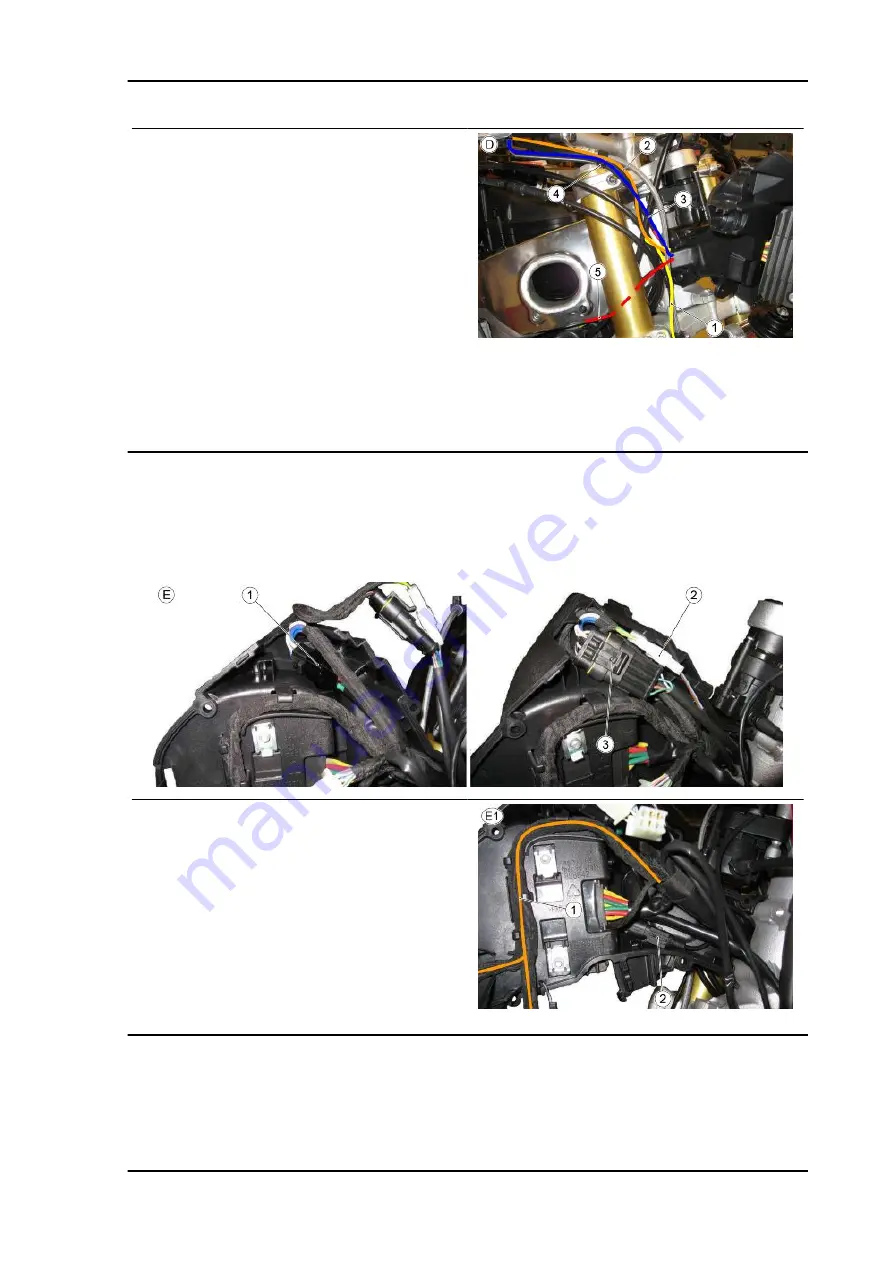
APRILIA TUONO V4 R 2010 Service Station Manual Download Page 101

TABLE D

1. Speed sensor cable harness routing inside the

cable grommet and between throttle cables and

frame

Ensure that the cable grommet is not

interfering with the steering damper

during its movement

2. Right switch cable harness routing

3. Rubber clamp

4. Front stop switch cable harness routing

5. Main cable harness routing

TABLE E - INSTRUMENT HOLDER SUPPORT

First connect the regulator connector (1) and place it as shown in the figure

Connect the stop connector (2) and then the right light switch connector (3) and place them

as shown in the figure.

TABLE E1 - INSTRUMENT HOLDER SUPPORT

Place the branch (1) in the correspond-

ing tongues as shown in the figure

Fit the front ABS sensor (2) as shown

in the figure

Place the clamps (3) to then fasten the

main cable harness.

TUONO V4 R

Electrical system

ELE SYS - 101

Summary of Contents for TUONO V4 R 2010

Page 1: ...SERVICE STATION MANUAL B043120 TUONO V4 R ...

Page 2: ...nd tested together with the actual vehicle itself All Aprilia Original Spare Parts undergo quality control procedures to guarantee reliability and durability The descriptions and illustrations given in this publication are not binding While the basic characteristics as described and illustrated in this booklet remain unchanged Aprilia reserves the right at any time and without being required to up...

Page 3: ...d changes in repair procedures are communicated to all aprilia Sales Outlets and its International Subsidiaries These changes will be introduced in the subsequent editions of the manual In case of need or further queries on repair and check procedures consult aprilia CUSTOMER DEPARTMENT which will be prepared to provide any information on the subject and any further communications on updates and t...

Page 4: ......

Page 5: ...OLS S TOOLS MAINTENANCE MAIN TROUBLESHOOTING TROUBL ELECTRICAL SYSTEM ELE SYS ENGINE FROM VEHICLE ENG VE ENGINE ENG POWER SUPPLY P SUPP SUSPENSIONS SUSP CHASSIS CHAS BRAKING SYSTEM BRAK SYS COOLING SYSTEM COOL SYS BODYWORK BODYW PRE DELIVERY PRE DE ...

Page 6: ...INDEX OF TOPICS CHARACTERISTICS CHAR ...

Page 7: ...TION OR EXPLOSION DO NOT ALLOW FUEL TO DISPERSE INTO THE ENVIRONMENT KEEP OUT OF THE REACH OF CHILDREN Hot components The engine and the exhaust system components become very hot and remain hot for some time after the engine has been switched off Before handling these components make sure that you are wearing insulating gloves or wait until the engine and the exhaust system have cooled down Coolan...

Page 8: ... electrolyte and hydrogen gas CAUTION THE BATTERY ELECTROLYTE IS TOXIC CORROSIVE AND AS IT CONTAINS SULPHURIC ACID MAY CAUSE BURNING IF IT COMES INTO CONTACT WITH THE SKIN WHEN HANDLING BATTERY ELECTROLYTE WEAR TIGHT FITTING GLOVES AND PROTECTIVE APPAREL IN THE EVENT OF SKIN CONTACT WITH THE ELECTROLYTIC FLUID RINSE WELL WITH PLENTY OF CLEAN WATER IT IS PARTICULARLY IMPORTANT TO PROTECT YOUR EYES ...

Page 9: ...a SPARE PARTS Comply with lubricant and consumables use guidelines Lubricate parts whenever possible before reassembling them When tightening nuts and screws start either from the components with the largest diameter or from the innermost components proceeding diagonally Tighten nuts and screws in suc cessive steps before applying the tightening torque Always replace self locking nuts washers seal...

Page 10: ...A WHEEL TO LOCK OR COMPROMISING VEHICLE HANDLING THIS MAY LEAD TO FALLS WITH THE RISK OF SERIOUS INJURY OR DEATH Running in Running the engine in correctly is essential for ensuring engine longevity and functionality Twisty roads and gradients are ideal for running in the engine brakes and suspension effectively Vary your riding speed during the running in period This ensures that components opera...

Page 11: ...re S production plant S Scorzè XXXXXX serial number 6 digits CHASSIS NUMBER The chassis number is stamped on the right hand side of the headstock ENGINE NUMBER The engine number is printed on the base of the engine crankcase left hand side Engine No Dimensions and mass DIMENSIONS Specification Desc Quantity Max length 2 065 mm 81 30 in Max width 820 mm 32 28 in Max height at handlebar 1 090 mm 42 ...

Page 12: ...ith oil radiator Oil pump Dual trochoidal pump lubrication cooling Oil filter With external cartridge filter Cooling Fluid Cooling system 3 way thermostatic valve cooling radiator with electric fan and expansion tank Coolant pump Centrifugal bearingless aspirating pump with integrated ce ramic gasket Air filter Paper Alternatively Air filter In cotton Transmission GEAR RATIOS Specification Desc Qu...

Page 13: ...LED Turn indicators 12V 10W White light Rear daylight running light stop light LED License plate light 12V 5W WARNING LIGHTS Specification Desc Quantity High beam light LED Right turn indicator LED Left turn indicator LED General warning LED Gear in neutral LED Side stand down LED Fuel reserve LED ABS NOT ENABLED Frame and suspensions CHASSIS Specification Desc Quantity Type Aluminium dual beam ch...

Page 14: ...in metal braid Rear disc type 220 mm diam 8 66 inches 2 piston callipers 32 mm diam 1 25 inches pump with built in tank and metal braid pipe Wheels and tyres WHEEL RIMS Specification Desc Quantity Front wheel rim 3 50 x 17 Rear wheel rim 6 00 x 17 TYRES Specification Desc Quantity Tyre model Pirelli DIABLO Rosso Corsa Michelin Power Pure Metzeler RACETEC K3 Pirelli Diablo Super Corsa SP Front tyre...

Page 15: ...Throttle body diameter 48 mm 1 89 in Type Electronic injection multipoint 2 throttle bodies motorised ride by wire 2 dynamic air intakes Selectable multimap Tightening Torques Chassis Front side OIL RADIATOR pos Description Type Quantity Torque Notes 1 Screws fastening oil radiator to mounting bracket M6 1 7 Nm 5 16 lbf ft TUONO V4 R Characteristics CHAR 15 ...

Page 16: ...Notes 1 TEFL screw fasten onto Fork Hubs M6x40 4 10 Nm 7 37 lbf ft 2 Screw Pumping member pin fixing to the stem base 2 30 Nm 22 13 lbf ft 3 Upper cover 2 20 Nm 14 75 lbf ft 4 Upper cover locking nut 2 20 Nm 14 75 lbf ft Characteristics TUONO V4 R CHAR 16 ...

Page 17: ...5 Nm 18 43 lbf ft 4 Screws fastening lower yoke to stan chions M8 4 25 Nm 18 43 lbf ft 5 Headstock counter lock ring M35x1 1 Manual 90 6 Headstock lock ring M35x1 1 40 Nm 29 5 lbf ft Steering damper fastening screw 2 10 Nm 7 37 lbf ft Loctite 243 FRONT WHEEL pos Description Type Quantity Torque Notes 1 Front wheel spindle nut M25x1 5 1 80 Nm 59 lbf ft 2 Front brake disc fixing screws M8 6 6 30 Nm ...

Page 18: ...rque Notes 1 Front brake calliper fixing screws M10x1 25 2 2 50 Nm 36 88 lbf ft FRONT BRAKE PUMP pos Description Type Quantity Torque Notes 1 Screw fastening front brake fluid res ervoir to bracket M6 1 7 Nm 5 16 lbf ft Characteristics TUONO V4 R CHAR 18 ...

Page 19: ... M6 2 10 Nm 7 37 lbf ft 5 Front brake lever pin fixing screw M6 1 10 Nm 7 37 lbf ft HANDLEBAR AND CONTROLS pos Description Type Quantity Torque Notes 1 Anti vibration counterweight fastener M6 1 10 Nm 7 37 lbf ft 2 Throttle control fixing screw M5 2 6 Nm 4 42 lbf ft 3 Left light switch M5 2 2 Nm 1 47 lbf ft 4 Mirror supporting pin M10 2 40 Nm 29 50 lbf ft 5 Mirror supporting nut M16x1 2 40 Nm 29 5...

Page 20: ...iption Type Quantity Torque Notes 1 Screws fastening the headlamp to the upper fairing fastener M5 2 3 Nm 1 47 lbf ft 2 Screws fastening headlamp to front fairing M5 4 4 Nm 2 95 lbf ft Characteristics TUONO V4 R CHAR 20 ...

Page 21: ...2 Nm 1 47 lbf ft 3 Screws fastening instrument panel mounting to chassis M6 4 8 Nm 5 9 lbf ft 4 Voltage regulator fixing screw M6 1 8 Nm 5 90 lbf ft FRONT MUDGUARD pos Description Type Quantity Torque Notes 1 Front mudguard fixing screws M5 4 4 Nm 2 95 lbf ft 2 Lug fixing screw M5 2 4 Nm 2 95 lbf ft 3 Screws fastening the lower fairing to the lug M5 2 2 4 Nm 2 95 lbf ft TUONO V4 R Characteristics ...

Page 22: ... Top fairing fixing screw M4 1 3 Nm 2 21 lbf ft 2 Front turn indicator fixing screw M6 2 2 5 Nm 1 84 lbf ft CLUTCH LEVER pos Description Type Quantity Torque Notes 1 Clutch lever collar fixing screws M6 1 10 Nm 7 37 lbf ft Characteristics TUONO V4 R CHAR 22 ...

Page 23: ...cket to chassis M6 2 10 Nm 7 37 lbf ft 2 Screws fastening water radiator to mounting bracket M6 2 7 Nm 5 16 lbf ft 3 Screw fastening pipe grommet for By pass water hose M5 1 6 Nm 4 42 lbf ft 4 Screws fastening electric fan to wa ter radiator M4 6 2 Nm 1 47 lbf ft TUONO V4 R Characteristics CHAR 23 ...

Page 24: ...ype Quantity Torque Notes 1 Screws fastening the stand to the chassis M10 2 45 Nm 33 19 lbf ft Loct 243 2 Linear switch retainer M5 2 4 Nm 2 95 lbf ft Rear stand bushing fastening screws M6 2 7 Nm 5 16 lbf ft Characteristics TUONO V4 R CHAR 24 ...

Page 25: ... M5 8 3 Nm 2 21 lbf ft 4 Front screws fastening the tank to the chassis M6 1 8 Nm 5 9 lbf ft 5 Rear screws fastening the tank to the rear chassis M6 2 7 Nm 5 16 lbf ft 6 Screws fastening plastic fuel pipe mounting M5 1 2 5 Nm 1 84 lbf ft 7 Left fairing mounting bracket fixing screws M5 1 3 Nm 2 21 lbf ft 8 Screws fastening structural tank mounting to tank M6 4 3 Nm 2 21 lbf ft Central screw fasten...

Page 26: ...M8 2 2 25 Nm 18 43 lbf ft Fix with Loctite 243 2 Screws fastening passenger foot pegs to saddle mounting M8 2 2 18 Nm 13 27 lbf ft Fix with Loctite 243 3 Rider heelrest fixing screws M6 2 2 8 Nm 5 90 lbf ft 4 Passenger heelrest fixing screws M6 2 2 8 Nm 5 90 lbf ft Characteristics TUONO V4 R CHAR 26 ...

Page 27: ...ushing M18x1 5 1 12 Nm 8 85 lbf ft 8 Upper rear right hand mount M10 1 50 Nm 36 88 lbf ft 9 Right fairing spacer M6 1 10 Nm 7 37 lbf ft Loct 243 10 Upper rear left hand engine mount fastener screws M8 3 25 Nm 18 44 lbf ft Screw fastening the ground cable to the left side chassis M6 1 6 Nm 4 42 lbf ft REAR CHASSIS pos Description Type Quantity Torque Notes 1 Saddle mounting fixing screws M10 4 50 N...

Page 28: ...S pos Description Type Quantity Torque Notes 1 Nut fastening saddle lock to tail fair ing M22x1 5 1 5 Nm 3 69 lbf ft 2 Lock lever self tapping screw M4 1 2 Nm 1 47 lbf ft Characteristics TUONO V4 R CHAR 28 ...

Page 29: ...6 2 6 Nm 4 42 lbf ft 4 Shear head screw to the left of the ignition lock M8 1 Manual Tighten until the head shears off 5 Right hand ignition lock screw M8 1 20 Nm 14 75 lbf ft CENTRAL ELECTRICAL SYSTEM pos Description Type Quantity Torque Notes 1 Upper Silentblock nut demand sen sor mounting bracket M6 1 5 Nm 3 69 lbf ft 2 Demand sensor fixing screw to mounting plate SWP 4 9 4 1 2 Nm 0 88 lbf ft T...

Page 30: ...25 Nm 18 44 lbf ft 5 Gearbox linkage joint to gearbox lev er fastener 1 8 Nm 5 90 lbf ft Loct 6 Gearbox linkage nut to quick shift fastener 1 8 Nm 5 90 lbf ft 7 TBEI screws M6x20 2 8 Nm 5 90 lbf ft Smear waterproof grease between the O rings and the Quick Shift uniball NOTE ONCE REASSEMBLY IS COMPLETED CENTRE TO CENTRE DISTANCE BETWEEN UNIBALL AND JOINT MUST BE APPROX 180mm 7 09in Characteristics ...

Page 31: ... Quantity Torques Notes 1 Pinion protector casing fixing screws M6 3 8 Nm 5 9 lbf ft 2 Gearbox lever pin fixing screw M6 1 10 Nm 7 37 lbf ft 3 Gearbox lever fixing screws M6 1 10 Nm 7 37 lbf ft TUONO V4 R Characteristics CHAR 31 ...

Page 32: ... Silencer clamp fixing screw M6 1 10 Nm 7 37 lbf ft 3 Screw fastening silencer to right hand footpeg mounting M8 1 25 Nm 18 44 lbf ft 4 Screw fastening silencer to central lower fairing bracket M8 1 20 Nm 14 75 lbf ft 5 Cosmetic silencer shield fixing screw M5 2 5 Nm 3 69 lbf ft 6 Oxygen sensor fastener M18x1 5 1 38 Nm 28 03 lbf ft 7 Fastener screw for cable grommet for exhaust butterfly valve cab...

Page 33: ...HEEL pos Description Type Quantity Torque Notes 1 Rear wheel spindle nut M25x1 5 1 120 Nm 88 5 lbf ft 2 Screws fastening sprocket on sprocket mount M10 5 50 Nm 36 88 lbf ft TUONO V4 R Characteristics CHAR 33 ...

Page 34: ...pe Quantity Torque Notes 1 Rear brake disc fixing screws M8 5 30 Nm 22 13 lbf ft Loct 243 2 Screw fastening odometer sensor onto rear brake calliper mounting M6 1 12 Nm 8 85 lbf ft 3 Rear brake calliper mounting plate lock pin M12 1 50 Nm 36 88 lbf ft Loct 243 4 Rear calliper fixing screw M5 2 25 Nm 18 44 lbf ft 5 Brake pipe clamp fixing screw M5 2 4 Nm 2 95 lbf ft Brake pipe bracket fixing screw ...

Page 35: ...M20x1 5 1 65 Nm 47 94 lbf ft AGIP GREASE SM2 4 Chain casing fixing screws M5 2 4 Nm 2 95 lbf ft 5 Front chain guide fixing screw M5 1 4 Nm 2 95 lbf ft 6 Rear chain guide fixing nut M6 1 7 Nm 5 16 lbf ft 7 Chain skid fixing screws M5 2 2 Nm 1 47 lbf ft Lower chain slider fixing screws M6 2 10 Nm 7 37 lbf ft Chain guide fixing screw M6 1 8 Nm 5 90 lbf ft TUONO V4 R Characteristics CHAR 35 ...

Page 36: ...ity Torque Notes 1 Upper shock absorber fixing screw M10 1 50 Nm 36 88 lbf ft 2 Dual connecting rod fixing screw M10 3 50 Nm 36 88 lbf ft 3 Screw fastening single connecting rod to chassis M10 1 50 Nm 36 88 lbf ft Characteristics TUONO V4 R CHAR 36 ...

Page 37: ...ription Type Quantity Torque Notes 1 Rear mudguard fixing screws M6 2 3 Nm 2 21 lbf ft 2 License plate light fixing screws M4 1 1 Nm 0 74 lbf ft 3 Reflector fixing nuts M4 2 1 Nm 0 74 lbf ft 4 Screws fastening rear license plate holder to front license plate holder SWP 3 9 4 1 Nm 0 74 lbf ft 5 Screws fastening rear license plate holder to front license plate holder SWP 4 9 2 2 Nm 1 47 lbf ft Screw...

Page 38: ...side fairings to tail fairing M5 1 1 1 Nm 0 73 lbf ft 3 Screws fastening the grab handle shell SWP 3 9 11 1 5 Nm 1 10 lbf ft 4 Rear screws fastening grab handle to taillight support bracket M6 2 8 Nm 5 90 lbf ft 5 Front screws fastening grab handle to saddle support bracket M6 2 8 Nm 5 90 lbf ft Characteristics TUONO V4 R CHAR 38 ...

Page 39: ...s 1 Screws and nuts for fastening li cense plate holder to saddle mount ing plate M6 2 4 Nm 2 95 lbf ft 2 Lower saddle mounting fastener fix ing screws M5 5 3 Nm 2 21 lbf ft 3 Battery bracket fixing screws M5 2 2 Nm 1 47 lbf ft TUONO V4 R Characteristics CHAR 39 ...

Page 40: ...ne speed sensor fixing screw 1 8 Nm 5 9 lbf ft 2 TE flanged screw M6x20 1 12 Nm 8 85 lbf ft 3 Flanged TE screws M6x35 2 12 Nm 8 85 lbf ft 4 Flanged TE screws M6x22 16 12 Nm 8 85 lbf ft 5 Engine timing inspection cap 1 25 Nm 18 44 lbf ft Characteristics TUONO V4 R CHAR 40 ...

Page 41: ...VER pos Description Type Quantity Torque Notes 1 Head cover fixing screws 6 10 Nm 7 37 lbf ft 2 Coil fixing screws 4 8 Nm 5 9 lbf ft Loct 243 3 Spark plugs 4 12 Nm 8 85 lbf ft TUONO V4 R Characteristics CHAR 41 ...

Page 42: ... stud bolts 8 10 Nm 7 37 lbf ft 2 Camshaft cam tower fixing screws M6x45 20 12 Nm 8 85 lbf ft 3 Reed valve cover fixing screws 6 6 Nm 4 42 lbf ft 4 Water outlet union fixing screw 2 12 Nm 8 85 lbf ft Loct 243 5 Flanged head nut 12 30 55 Nm 22 13 40 56 lbf ft Molykote spray on thread and under head 6 Head fastener screw chain side M6x55 4 12 Nm 8 85 lbf ft Characteristics TUONO V4 R CHAR 42 ...

Page 43: ...e Notes 1 Screws fastening the timing system gear on the intake shaft M8 4 30 Nm 22 13 lbf ft Loct 243 2 Skid fastener screws M8 2 20 Nm 14 75 lbf ft Loct 243 3 Skid fastener screws M6x18 2 10 Nm 7 37 lbf ft Loct 243 TUONO V4 R Characteristics CHAR 43 ...

Page 44: ...the head with Molykote 2 Fastener ring nut for alternator side timing sprocket 1 100 Nm 73 76 lbf ft Loct 243 3 Primary sprocket fixing ring nut 1 200 Nm 147 51 lbf ft Loct 243 4 Alternator fixing screw M12x1 25 1 120 Nm 88 51 lbf ft 5 Tone wheel fixing screw M8x1 25 1 30 Nm 22 13 lbf ft Loct 3M or 270 Characteristics TUONO V4 R CHAR 44 ...

Page 45: ...e thread and un der the head 5 Crankcase fixing screw M8x70 4 25 Nm 18 44 lbf ft Lubricate the thread and under the head 6 Crankcase fixing screw M8x35 3 25 Nm 18 44 lbf ft Lubricate the thread and under the head 7 Crankcase fixing screw M6x45 2 10 Nm 7 37 lbf ft Lubricate the thread and under the head 8 Crankcase fixing screw M6x20 5 10 Nm 7 37 lbf ft Lubricate the thread and under the head 9 Cra...

Page 46: ... M6x16 3 10 Nm 7 37 lbf ft Loct 243 3 Flange fixing screws M8x25 6 25 Nm 18 44 lbf ft 4 Index lever fixing screw M6 1 10 Nm 7 37 lbf ft Loct 243 5 Pinion retainer 1 50 Nm 36 88 lbf ft Loct 243 6 Screw retaining pre selector on crankcase 1 25 Nm 18 44 lbf ft Loct 270 Gear indicator fixing screw M5x15 2 6 Nm 4 42 lbf ft Characteristics TUONO V4 R CHAR 46 ...

Page 47: ...t 1 150 Nm 110 63 lbf ft Loct 243 2 Clutch spring fastener screw M6 6 10 12 Nm 7 38 8 85 lbf ft IGNITION UNIT pos Description Type Quantity Torque Notes 1 Hex headed nut cl 10 type 2 ISO 8674 M10x1 1 50 Nm 36 88 lbf ft Loct 243 TUONO V4 R Characteristics CHAR 47 ...

Page 48: ... M6x25 6 12 Nm 8 85 lbf ft 2 Cover fastener screws alternator side M6x40 2 12 Nm 8 85 lbf ft 3 Blow by union fastener screws M5x16 3 7 Nm 5 16 lbf ft Stator fixing screw UNI 5931 CL8 8 M6x25 3 10 Nm 7 37 lbf ft Loct 243 Flanged screw M5x12 1 6 Nm 4 42 lbf ft Loct 243 Characteristics TUONO V4 R CHAR 48 ...

Page 49: ...x22 4 12 Nm 8 85 lbf ft 5 Oil sump fixing screws M6x25 1 12 Nm 8 85 lbf ft 6 Screws fastening the pump to the crankcase M6 5 1 10 Nm 7 37 lbf ft 7 Oil pipe union fixing screw M6 1 8 Nm 5 90 lbf ft Loct 243 Screw fastening the diffuser in the oil sump 1 10 Nm 7 37 lbf ft SECONDARY AIR SYSTEM pos Description Type Quantity Torque Notes 1 Secondary air system solenoid screws 2 10 Nm 7 37 lbf ft TUONO ...

Page 50: ...an alternative to the recommended product use top brand grease for roller bearings with an operating temperature range of 30 C 140 C 22 F 284 F a drop point of 150 C 230 C 302 F 446 F high corrosion protection qualities and good water and rust resist ance AGIP PERMANENT SPEZIAL Coolant Ready for use mixed biodegradable cool ant with long life technology and char acteristics red Freezing protection...

Page 51: ...INDEX OF TOPICS SPECIAL TOOLS S TOOLS ...

Page 52: ...res code Description 020845Y Engine support 020846Y Retaining tray plastic caps 020913Y Flywheel extractor 020914Y Flywheel retainer 020849Y Clutch retainer 020850Y Primary gear lock Special tools TUONO V4 R S TOOLS 52 ...

Page 53: ...0852Y Crankshaft timing pin 020853Y Intake valve spring compressor 020854Y Exhaust valve spring compressor 020855Y Lever for engaging the chain tensioner 020856Y Piston installation ring 020857Y Crankshaft bearing U bolt TUONO V4 R Special tools S TOOLS 53 ...

Page 54: ...he pistons in the cyl inders AP8140199 Tool panel 020859Y Panel graphics 8140426 Hooks for panel 020860Y Engine support extension 020861Y Countershaft bushing punch 020862Y Gearbox control rod roller cage fitting punch Special tools TUONO V4 R S TOOLS 54 ...

Page 55: ...e fitting punch 020864Y Engine mounting plate 020865Y Support for camshaft gear on head 020883Y Tool for fitting removing the timing chain tensioner 020709Y Engine support AP8140187 Engine support stand 020376Y Adapter handle TUONO V4 R Special tools S TOOLS 55 ...

Page 56: ...ription 020363Y 20 mm Oil seal guide 020364Y 25 mm Guide 020359Y 42 x 47 mm punch 020431Y Valve oil seal extractor AP8140180 Extractor for bushings AP8140179 Valve spring compressor Special tools TUONO V4 R S TOOLS 56 ...

Page 57: ...box shaft 020877Y Pliers for clamps AP8140146 Weight AP8140189 Oil seal fitting tool for Ø 43 mm 1 69 in orifices AP8140149 Protection for fitting operations AP8140190 Tool for steering tightening 020888Y Pliers for pre fill pipe TUONO V4 R Special tools S TOOLS 57 ...

Page 58: ... code Description 020889Y Pumping member ring nut locking span ner 020890Y Pumping member stanchion support rod AP8140181 Fuel pressure checking tool 020680Y TXB Navigator Special tools TUONO V4 R S TOOLS 58 ...

Page 59: ...INDEX OF TOPICS MAINTENANCE MAIN ...

Page 60: ...ITIONS OFF ROAD OR FOR TRACK USE I INSPECT AND CLEAN ADJUST LUBRICATE OR REPLACE IF NECESSARY C CLEAN R REPLACE A ADJUST L LUBRICATE 1 Check at each engine start 2 Check and clean and adjust or replace if necessary before every journey 3 Check and clean and adjust or replace if necessary every 1000 Km 621 mi 4 Replace every 2 years 5 Replace every 4 years 6 Every 5000 Km 3107 mi if the vehicle is ...

Page 61: ...ration buffers I I Tyres pressure wear 2 I I I I I Wheels 6 I I I I I Tightening torques 6 I I I I I Tightening of clutch cover flywheel and oil sump screws I I I I I Fault warning light on instrument panel 1 Fuel lines 5 I I I I Clutch wear 7 I I Brake pad wear 2 I I I I I Spark plug FRONT SPARK PLUGS Remove the base of the air filter box Undo and remove the screw Slide off the front coil Unscrew...

Page 62: ... is on a level surface Check via the inspection glass in the crankcase that the oil level is near the upper marking Upper marking Max level Lower marking Min level If this is not the case top up the oil im mediately through the filler plug CAUTION NEVER ALLOW THE OIL LEVEL TO DROP BELOW THE MINIMUM LEVEL OR FILL ABOVE THE MAXIMUM LEVEL IF YOU DO NOT COMPLY WITH THE MINIMUM AND MAX IMUM OIL LEVELS ...

Page 63: ... the filler cap Warm up the engine up by running it for a few minutes then switch it off After thirty seconds check the level in the sight glass Top up if necessary CAUTION NEVER ALLOW THE OIL LEVEL TO DROP BELOW THE MINIMUM LEVEL OR FILL ABOVE THE MAXIMUM LEVEL IF YOU DO NOT COMPLY WITH THE MINIMUM AND MAX IMUM OIL LEVELS THE ENGINE COULD BE SERIOUSLY DAMAGED Engine oil filter Replace the engine ...

Page 64: ...crew and remove the eight air filter box cover screws Fit a suitably sized shim behind the fil ter box cover Lift the filter box cover on which the control unit is installed Do not rotate the cover excessively to avoid straining the pipes and cables Plug the intake duct opening with clean paper See also Fuel tank Unscrew and remove the three air filter screws Remove the filter and replace it with ...

Page 65: ...shaft taking care not to lose the O ring See also Removing the throttle body Spark plug Head cover removal Use a feeler gauge to check the clear ance between the cam of the shaft and the relative tappet for both front head shafts Characteristic Acceptable values with control clearance be tween cam and valve intake 0 10 0 15 mm 0 0039 0 0059 in ex haust 0 20 0 25 mm 0 0079 0 0098 in TUONO V4 R Main...

Page 66: ...lug Head cover removal Use a feeler gauge to check the clear ance between the cam on the shaft and the relative tappet for both rear head shafts Characteristic Acceptable values with control clearance be tween cam and valve intake 0 10 0 15 mm 0 0039 0 0059 in ex haust 0 20 0 25 mm 0 0079 0 0098 in Maintenance TUONO V4 R MAIN 66 ...

Page 67: ...over Turn the crankshaft from the hole on the clutch cover Move cylinder piston 1 left rear piston to the TDC overlap Turn the crankshaft 150 in the direc tion of engine rotation direction of trav el CAUTION WHEN TURNING THE CRANKSHAFT PREVIOUSLY RE MOVE ALL THE SPARK PLUGS Insert the pin from the flywheel side in the hole in the crankshaft NOTE THE SPECIAL TOOL IS ONLY USED FOR IDENTIFYING THE CO...

Page 68: ...screw and remove the camshaft gear screw Remove the crankshaft locking tool Specific tooling 020850Y Primary gear lock 020848Y Flywheel retainer Repeat the following operations move cylinder piston 1 left rear piston to TDC turn the crankshaft 150 in the direction of engine rotation direction of travel in order to align the hole on the intake camshaft with the specific hole on the U bolt this ensu...

Page 69: ... and remove the second in take camshaft gear screw Leave the gear on the camshaft Specific tooling 020848Y Flywheel retainer 020850Y Primary gear lock Install the specific camshaft gear sup port tool Fix it to the head using the two screws 1 Move the gear from the camshaft to the tool Specific tooling 020865Y Support for camshaft gear on head Unscrew and remove the eight screws 2 proceeding in sta...

Page 70: ...nent to achieve the cor rect valve clearance Refer to the table Calibrated pad thickness es to identify the suitable thickness Fit the tappet See also Calibrated pad thickness NOTE THIS ENGINE HAS CAMSHAFTS OF THE EXHAUST VALVES WITH CLEARANCE RECOVERY Install the intake and exhaust camshafts on the front head bearing in mind that the exhaust camshaft gear tooth indicated with a dot is meshed with...

Page 71: ...et Move the gear from the mounting tool to the camshaft Unscrew and remove the two screws 1 Remove the tool Specific tooling 020865Y Support for camshaft gear on head Fit the U bolt and the oil pipe Tighten the two U bolt screws 1 and the screw 2 that was not fitted previ ously Align the intake camshaft with the spe cific hole on the U bolt Insert the specified pin Specific tooling 020851Y Camshaf...

Page 72: ...ock Remove the two crankshaft and cam shaft reference pins Turn the crankshaft until the gear screw covered by the head when the hole on the camshaft gear is aligned with the hole on the U bolt is visible Block crankshaft rotation using one of the specific tools Apply Loctite 243 thread lock on the thread of the second gear fastener screw This screw must be replaced at each reassembly Tighten the ...

Page 73: ...the valve clearance adjustment procedure Rear cylinder head valves Check the rear valve head clearance and restore the correct clearance values if necessary proceeding as described below Remove the rear head cover and the clutch cover Move cylinder piston 1 left rear piston to the TDC Turn the crankshaft 450 one complete turn 90 in the direction of motor rotation direction of travel Insert the pin...

Page 74: ...nd remove the camshaft gear screw Remove the crankshaft locking tool Specific tooling 020850Y Primary gear lock 020848Y Flywheel retainer Repeat the following operations move cylinder piston 1 left rear piston to TDC turn the crankshaft by 450 one com plete turn 90 in the direction of en gine rotation direction of travel to align the hole on the intake camshaft with the specific hole on the U bolt...

Page 75: ...nd remove the second in take camshaft gear screw Leave the gear on the camshaft Specific tooling 020848Y Flywheel retainer 020850Y Primary gear lock Install the specific camshaft gear sup port tool Fix it to the head using the two screws 1 Move the gear from the camshaft to the tool Specific tooling 020865Y Support for camshaft gear on head Unscrew and remove the eight screws 2 proceeding in stage...

Page 76: ...mponent to achieve the cor rect valve clearance Refer to the table Calibrated pad thickness es to identify the suitable thickness Fit the tappet See also Calibrated pad thickness NOTE THIS ENGINE HAS CAMSHAFTS OF THE EXHAUST VALVES WITH CLEARANCE RECOVERY Install the intake and exhaust camshafts on the rear head remembering that the intake camshaft gear tooth indicated with a dot is inserted in th...

Page 77: ...et Move the gear from the mounting tool to the camshaft Unscrew and remove the two screws 1 Remove the tool Specific tooling 020865Y Support for camshaft gear on head Fit the U bolt and the oil pipe Tighten the two U bolt screws 1 and the screw 2 that was not fitted previ ously Align the intake camshaft with the spe cific hole on the U bolt Insert the specified pin Specific tooling 020851Y Camshaf...

Page 78: ...ock Remove the two crankshaft and cam shaft reference pins Turn the crankshaft until the gear screw covered by the head when the hole on the camshaft gear is aligned with the hole on the U bolt is visible Block crankshaft rotation using one of the specific tools Apply Loctite 243 thread lock on the thread of the second gear fastener screw This screw must be replaced at each reassembly Tighten the ...

Page 79: ...e repeat the timing operations Specific tooling 020851Y Camshaft timing pin 020852Y Crankshaft timing pin Check if the clearance between the cam on the shaft and the tappet is correct If not repeat the valve clearance adjustment procedure Calibrated pad thickness Pad thicknesses for adjusting valve clearance correctly 1 75 mm 0 0689 in 1 80 mm 0 0709 in 1 85 mm 0 0728 in 1 90 mm 0 0748 in 1 95 mm ...

Page 80: ...45 mm 0 0964 in 2 50 mm 0 0984 in 2 55 mm 0 1004 in 2 6 mm 0 1024 in 2 65 mm 0 1043 in 2 7 mm 0 1063 in 2 75 mm 0 1083 in 2 8 mm 0 1102 in 2 85 mm 0 1122 in 2 9 mm 0 1142 in 2 95 mm 0 1161 in 3 mm 0 1181 in 3 05 mm 0 1201 in 3 10 mm 0 1220 in 3 15 mm 0 1240 in Maintenance TUONO V4 R MAIN 80 ...

Page 81: ...INDEX OF TOPICS TROUBLESHOOTING TROUBL ...

Page 82: ...OW IS SELECTED AND IS DISPLAYED PRESS THE KEY TO OBTAIN FURTHER INFORMATION ABOUT THE ERROR THEN GO TO THE ELECTRICAL SYSTEM CHECKS AND CONTROLS CHAPTER AND READ THE INFORMATION CONCERNING THE DEFECTIVE COMPONENT 5 ACCORDING TO WHAT IS INDICATED ABOUT THE ERROR S PROCEED AS SUG GESTED AND SOLVE THE PROBLEM 6 WAS THE PROBLEM SOLVED BY REPLACING THE MARELLI CONTROL UNIT YES go to 7 NO go to 8 7 READ...

Page 83: ...C 15 IN THE ENGINE PARAMETER READING WITH ENGINE AT IDLE AND ENGINE TEMPERATURE 65 c FRONT THROTTLE CORRECTION OR REAR THROTTLE CORRECTION WITH ENGINE AT IDLE ARE THE PARAMETERS INCLUDED WITHIN 0 8 0 8 INTERVAL AND IN THE SAME SCREEN PAGE ARE THE FRONT THROT POT 1 DEGREES AND REAR THROT POT 1 DEGREES WITH EN GINE AT IDLE OR A 0 5 CAUTION THE DIFFERENCE OF THE THROTTLE CORRECTION VALUES BETWEEN THE...

Page 84: ... 3 NO go to FUEL PUMP CHECK 3 THE DIAGNOSIS INSTRUMENT COMMUNICATES WITH THE CONTROL UNIT THAT IS AFTER SELECTING FUEL INJECTION AND FOLLOWING THE INSTRUCTION WITH KEY SET TO ON THE PARAMETERS STATUSES ETC ARE READ YES go to 4 NO go to DIAGNOSIS INSTRUMENT CONNECTION CHECK 4 WITH DIAGNOSIS INSTRUMENT DEVICES ACTIVATION SCREEN PAGE INJEC TOR ICON CARRY OUT ACTIVATION OF AN INJECTOR IT IS ADVISED TO...

Page 85: ...SOR IN THE FRAME INTERNAL FRONT NICHE IN VERTICAL POSI TION YES go to 13 NO go to 14 13 REFER TO THE CHAPTER ELECTRICAL SYSTEM CHECKS AND CONTROLS FALL SENSOR INDICATION ON DIAGNOSIS INSTRUMENT ALWAYS TIP OVER END 14 SET THE SENSOR TO THE CORRECT POSITION END 15 REFER TO THE CHAPTER ELECTRICAL SYSTEM CHECKS AND CONTROLS RUN STOP SWITCH INDICATION ON DIAGNOSIS INSTRUMENT ALWAYS TIP OVER END 16 CHEC...

Page 86: ...L SYSTEM CONNECTOR If there is continuity go to PROTECTION RELAY 19 CHECK if there is not continuity restore cable harness END See also Control unit CHECK FUEL PUMP 1 WITH KEY SET TO ON DISCONNECT THE CONNECTOR AND CHECK THAT THERE IS BATTERY VOLTAGE ON PIN 1 YES go to 2 NO go to 4 2 CHECK FUEL PUMP CONNECTOR AND CHECK THAT AT PIN 2 THERE IS GROUND CONTINUITY YES go to 3 NO go to 5 3 CHECK ON CONN...

Page 87: ... to 3 NO go to 6 3 WITH KEY SET TO ON IS THERE VOLTAGE ON ORANGE CABLE OF THE INJEC TION RELAY CONNECTOR ON THE CABLE HARNESS SIDE YES go to 4 NO go to 7 4 CHECK CORRECT OPERATION OF THE RELAY THAT IS PROVIDING VOLTAGE ON THE CORRESPONDING PIN TO THE RED BROWN CABLE AND GROUND ON SPE CIFIC PIN TO THE BROWN BLACK CABLE IS THERE CONTINUITY BETWEEN THE OTHER TWO RELAY PINS YES go to 5 NO replace the ...

Page 88: ...nuity go to 5 if there is not continuity restore cable harness END 5 WITH KEY SET TO OFF CHECK IF THERE IS VOLTAGE ON RED WHITE CABLE ON THE KEY SWITCH CONNECTOR YES go to 6 NO restore the cable harness END 6 WITH KEY SET TO ON AND CONNECTOR DISCONNECTED CHECK ON THE SWITCH SIDE IF THERE IS LACK OF CONTINUITY BETWEEN THE TWO PINS COR RESPONDING TO THE RED WHITE CABLE AND GREEN BLUE AND REPLACE THE...

Page 89: ...ICLE CABLE HAR NESS CONNECTOR YES go to 4 NO restore the cable harness END 6 CHECK CONTINUITY OF PINK BLACK CABLE BETWEEN SWITCH CONNECTOR AND PIN 4 OF THE CONTROL UNIT CHECKING ALSO THE ENGINE VEHICLE CABLE HARNESS CONNECTOR YES go to 4 NO restore the cable harness END 7 REPLACE THE STARTER BUTTON COMPONENT END TUONO V4 R Troubleshooting TROUBL 89 ...

Page 90: ...INDEX OF TOPICS ELECTRICAL SYSTEM ELE SYS ...

Page 91: ...t 2 Horn fixing screw M8 1 15 Nm 11 06 lbf ft 3 Screw fastening the voltage regula tor to the inner fairing M6 2 6 Nm 4 42 lbf ft 4 Shear head screw to the left of the ignition lock M8 1 Manual Tighten until the head shears off 5 Right hand ignition lock screw M8 1 20 Nm 14 75 lbf ft TUONO V4 R Electrical system ELE SYS 91 ...

Page 92: ...pe Quantity Torque Notes 1 Upper Silentblock nut demand sen sor mounting bracket M6 1 5 Nm 3 69 lbf ft 2 Demand sensor fixing screw to mounting plate SWP 4 9 4 1 2 Nm 0 88 lbf ft Components arrangement Key Electrical system TUONO V4 R ELE SYS 92 ...

Page 93: ...ure sensor 28 Quick Shift if fitted A RELAY CANNOT BE IDENTIFIED BASED ON THE FOLLOWING INDICATIONS ONLY THIS HAS TO BE DONE ALSO IDENTIFYING THE COLOUR OF THE RELAY CABLES RELAY LAYOUT Component position in the electrical circuit diagram Component name Location on the vehicle 07 Light logic relay Left side of the front support 65 High beam light relay Internal side left side of the front headlamp...

Page 94: ...wing cable harnesses and parts 1 Vehicle cable harness 1 Headlamp cable harness 1 License plate frame cable harness 1 Positive battery cable 1 Battery engine ground cable 1 Ignition switch 2 ABS speed sensor 1 Start up relay 4 Relays 1 Protection relay 1 Horn 1 Fall sensor optional equipment 1 Headlamp 1 Taillight 1 Instrument panel 1 Right rear view mirror with turn indicator 1 Left rear view mir...

Page 95: ... are various types of rubber blocks 1 Rubber ring for the protection relay 1 Rubber ring for fall sensor OPTIONAL EQUIPMENT 1 AMP Superseal connector mounting 1 Relay fall sensor mounting 1 Battery mounting bracket 3 T shaped bushing there are various types of T shaped bushings 2 Washer 3 5x20x1 5 washer 2 Spacers there are various types of spacers 1 Exhaust valve opening cable 1 Exhaust valve clo...

Page 96: ...nsor 1 Alternator 1 Starter motor N 4 Injectors Small parts and mountings 1 Control unit mounting 4 Large black 178x4 clamps 4 Self tapping 5x20 screws 3 Self tapping screws 3 Washers 3 Silentblocks 2 Self tapping screws 4 AMP Superseal connector mountings 1 Mounting for the Framatome connector 2 Small black clamps 1 Rubber clamp 1 Flanged M6x16 screw 1 Secondary air solenoid mounting 1 Secondary ...

Page 97: ...nector Demand sensor connectors Start up relay connector Rear speed sensor connector Fall sensor connector if fitted Safety relay connector Protection relay connector Injection relay connector Taillight connector Fuel pump connector Exhaust valve actuator connector Engine vehicle interface connector Flywheel connector Regulator connector Fan connectors Starter motor eyelet Stand switch connector R...

Page 98: ... the vehicle to stop or malfunction Obviously the correct connection of the other connectors is also important and essential for proper vehicle operation It is also important and essential that the instructions regarding the routing and fixing of the cable har ness in the various areas are followed meticulously in order to guarantee functionality and reliability Front side TABLE A RELAY AND FALL S...

Page 99: ...ed on the headlamp as indicated 1 Front headlamp 2 Front tail light connector 3 Relay with a relay socket rubber ring at 90 4 Left headlight connector 5 Right headlight connector 6 Cable harness vehicle interface connector 7 Left arrow 8 Right arrow TABLE C1 HEADLAMP PRE FITTING Check if the connectors tongues are well attached TUONO V4 R Electrical system ELE SYS 99 ...

Page 100: ... headlamp TABLE C3 HEADLAMP PRE FITTING Check that the connectors are correctly inserted after placing and tightening the clamps TABLE C4 HEADLAMP PRE FITTING Place the cable guides TABLE C5 HEADLAMP PRE FITTING Put the clamps on the cables of the front turn indicators Electrical system TUONO V4 R ELE SYS 100 ...

Page 101: ...ain cable harness routing TABLE E INSTRUMENT HOLDER SUPPORT First connect the regulator connector 1 and place it as shown in the figure Connect the stop connector 2 and then the right light switch connector 3 and place them as shown in the figure TABLE E1 INSTRUMENT HOLDER SUPPORT Place the branch 1 in the correspond ing tongues as shown in the figure Fit the front ABS sensor 2 as shown in the fig...

Page 102: ...nnectors 2 Lights relay connector 3 Front headlight connector 4 Horn terminals 5 Immobilizer antenna connector TABLE E3 INSTRUMENT HOLDER SUPPORT Group the several branches locking them by means of the slotted mounting 1 Key branch 2 Instrument panel branch 3 Immobilizer antenna branch 4 Slotted mounting Electrical system TUONO V4 R ELE SYS 102 ...

Page 103: ...STRUMENT HOLDER SUPPORT 1 Lights relay 2 Front headlight connector Insert the front headlamp connector in its housing paying attention that it is correctly placed TABLE F 1 Instrument panel 2 Washer 3 Rubber ring 4 Screw TUONO V4 R Electrical system ELE SYS 103 ...

Page 104: ...E STEERING Central part TABLE A VEHICLE CABLE HARNESS The main cable harness and the relay and fall sensor mounting must be fitted on the chassis before fitting the engine 1 Vehicle cable harness 2 Insert two screw clamps on the rigid section of the cable harness in the two holes on the right chassis beam NOTE CHECK CORRECT CONNECTION OF THE FAN RELAY SAFETY RELAY AND POSSIBLE FALL SENSOR OPTION A...

Page 105: ...ind the starter motor 2 Starter motor cable harness routing that must pass behind water pipe 3 Oil pressure sensor cable harness routing that must pass behind water pipe 4 Clamp 5 Oil pressure sensor 6 Starter motor eyelet 7 Washer 8 Nut CAUTION COVER MOTOR NUT AND SQUARE TERMINAL WITH WA TERPROOF DIELECTRIC GREASE TUONO V4 R Electrical system ELE SYS 105 ...

Page 106: ...CAUTION CHECK THAT THE CONNECTORS ARE CORRECTLY INSERTED AND THAT THE PURPLE SLIDE IS AT THE END OF THE STROKE CAUTION CHECK THAT THE CABLE ON THE STARTER MOTOR IS PLACED AS INDICATED TABLE C1 DEMAND SENSOR Check that the connectors are inserted correctly and that the security locks are in the locked position 1 Slave Demand cable harness routing creating a U bend in the cable harness 2 Master Dema...

Page 107: ...TABLE C2 DEMAND SENSOR 1 Demand sensor TUONO V4 R Electrical system ELE SYS 107 ...

Page 108: ...sup port and close the fairing in the upper part 1 Regulator connector TABLE E FANS 1 Left fan connector 2 Right fan connector TABLE E1 FANS 1 Fans TABLE F 1 Right branch 2 Left branch 3 Radiator support Electrical system TUONO V4 R ELE SYS 108 ...

Page 109: ...lve actuator connector 4 Clamp TABLE G1 EXHAUST VALVE ACTUATOR 1 Exhaust valve actuator 2 Heat protecting cover 3 Screws 4 T shaped bushings 5 Rubber blocks 6 Spacer TABLE G2 EXHAUST VALVE ACTUATOR 1 Closing cable 2 Opening cable Both Bowden cables must have the same voltage TUONO V4 R Electrical system ELE SYS 109 ...

Page 110: ...e pulley Finally tighten the lock nut on the set screw Operate on the adjuster screw of the opening ca ble until there is a cable voltage similar to the closing cable Finally tighten the lock nut on the set screw TABLE H PINION CASING AREA 1 Quick shift laying of cables IF APPLICABLE 2 Gear sensor cable harness routing 3 Oxygen sensor 4 Oxygen sensor cable harness routing 5 Stand switch cable harn...

Page 111: ... harness routing 5 Cable grommet Pass the cable harnesses behind the cable grommet that closes the two fuel breather pipes TABLE L OXYGEN SENSOR AND STAND SWITCH 1 Oxygen sensor cable harness routing 2 Stand switch cable harness routing 3 Cable guide TABLE M QUICK SHIFT IF APPLICABLE 1 Quick Shift cable harness routing TUONO V4 R Electrical system ELE SYS 111 ...

Page 112: ...arness routing 3 Stand switch cable harness routing 4 Oxygen sensor cable harness routing TABLE O 1 Quick Shift connector IF FITTED 2 Stand switch connector Set the connectors for stand switch Quick Shift and gear sensor under the two corrugated pipes Electrical system TUONO V4 R ELE SYS 112 ...

Page 113: ...mmets CAUTION PAY ATTENTION NOT TO INVERT THE ENGINE GND EYE LET FROM THE ENGINE CABLE HARNESS WITH THE CHASSIS GND EYELET FROM ENGINE CABLE HARNESS TABLE R BATTERY GROUND ENGINE CABLE 1 Clamp 2 Battery engine ground cable 3 Engine battery ground cable harness routing The engine battery ground cable harness must not be visible within the area indicated with a red triangle Back side TABLE A LICENSE...

Page 114: ...blue 4 License plate light grey rubber ring 5 2 8 mm 0 11 in Faston cable colours light blue and blue 6 Left rear turn indicator cable harness routing 7 Breather TABLE B SPEED SENSOR PRE FITTING 1 Speed sensor 2 Sensor fastener screw 3 Sensor cable harness routing in the cable grommet TABLE C SWINGARM AREA 1 Rubber clamp 2 Speed sensor cable harness 3 Rear brake switch cable harness Electrical sys...

Page 115: ...ble harness 3 Fit the individual fan fuse on battery mounting bracket tongue TABLE D1 REAR SADDLE MOUNTING AREA 1 Fit the individual fan fuse on battery mounting bracket tongue TABLE D2 REAR SADDLE MOUNTING AREA 1 Fuse box positioning on battery mounting bracket 2 Insert the fuse box in the two tongues on the battery mounting bracket TUONO V4 R Electrical system ELE SYS 115 ...

Page 116: ...on relay with relay socket rubber mount ing 3 Battery mounting bracket 4 Battery TABLE D4 REAR SADDLE MOUNTING AREA 1 Relay with relay socket rubber mounting 2 Protection relay with relay socket rubber mount ing 3 Battery mounting bracket 4 Battery Electrical system TUONO V4 R ELE SYS 116 ...

Page 117: ...ess routing 6 Insert the instrument panel diagnosis and the ECU diagnosis connectors in their specific seats TABLE D7 REAR SADDLE MOUNTING AREA 1 Start up relay 2 Starter relay connector 3 cable harness routing 4 Insert the screw clamp on the cable harness in the hole on the right side of the saddle mounting 5 Rubber clamp 6 Vehicle cable harness 7 Cable grommet 8 Battery positive cable harness ro...

Page 118: ...rt 1 Insert the screw clamp on the cable harness in the hole on the right side of the saddle mounting 2 Fuel pump connector 3 Clamps Internal part 4 Rear speed sensor connector 5 Rear brake switch connector Electrical system TUONO V4 R ELE SYS 118 ...

Page 119: ...NE WIRING HARNESS IN THE SECTION ELECTRICAL SYSTEM IN STALLING THE ENGINE ELECTRICAL SYSTEM AS REFERENCE FOR THE CONNECTOR OUT PUTS TABLE A ENGINE CABLE HARNESS 1 Rpm sensor 2 Starter motor 3 Generator 4 Gear sensor TABLE B ENGINE CABLE HARNESS LAYOUT Engine cable harness TUONO V4 R Electrical system ELE SYS 119 ...

Page 120: ...vehicle connector 2 Supports for coils connector TABLE D CONTROL UNIT MOUNTING PREP ARATION 1 Control unit 2 Fit the 3 silent blocks onto the seats on the mounting Then it is possible to fit the control unit by using the specific couples Electrical system TUONO V4 R ELE SYS 120 ...

Page 121: ...d with RED tape there are outputs 13 and 14 which are respectively mo torised throttle body 1 rear shorter branch and motorised throttle body 2 front longer branch TABLE E1 MOTORISED THROTTLE BODY CONNECTION PREPARATION AND SECON DARY AIR SOLENOID FITTING 1 Check that the connectors are inserted correctly and that the security locks are in the locked posi tion TABLE E2 MOTORISED THROTTLE BODY CONN...

Page 122: ...o the rubber manifolds with the specific clip on clamps Then fit the Motorised Throttle Body 1 rear on the rubber manifolds using the specific clip on clamps 1 Cable harness routing branch 4 under the fuel pipe TABLE F1 FITTING THE MOTORISED THROT TLE BODIES 1 Cable harness routing branch 2 in front of the branch 1 of the cable harness 2 Map Sensor 2 connector 3 Clamp together the corrugated pipe ...

Page 123: ...er part of the head cover 1 Engine speed sensor cable routing between the front motorised throttle body and the 3 way fitting 2 Water temperature sensor 3 Cable harness routing branch 4 under the 3 way fitting 4 Rubber clamp TABLE G2 WATER TEMPERATURE SENSOR AND INJECTORS CONNECTION At this point the injectors 2 output 5 and 4 output 6 can be connected the connector for injector 4 is GREY or there...

Page 124: ...e routing 2 Injector 1 cable harness connector output 16 BLACK CONNECTOR 3 Injector 3 cable harness connector output 17 GREEN connector 4 Coil 1 5 Coil 3 TABLE H COIL AND MAP SENSOR CONNECTION Once the filter box is assembled the coil and map sensor connections must be made The connectors for the 4 coils AMP Superseal male plug housing must be placed on the mountings that were previously fit on th...

Page 125: ...sor 2 cable harness connector output 11 5 Insert the screw clamp on the cable harness in the free hole on the filter box TABLE H3 COIL AND MAP SENSOR CON NECTION 1 Map Sensor 1 2 Map sensor 1 cable harness connector output 27 3 Engine speed sensor cable harness connector output 30 4 Clamp Once the Engine Speed Sensor out put 30 connector has been connec ted to its counterpart it must be TUONO V4 R...

Page 126: ...the position in dicated 1 Gear sensor cable harness connector output 15 2 Cable harness routing and connector position behind the corrugated pipes TABLE I1 GEAR SENSOR CONNECTION AND CABLE HARNESS ROUTING BY OXYGEN SENSOR The Oxygen Sensor output 19 ca ble harness must go down along the left side of the engine together with the Gear Sensor cable harness 1 Oxygen sensor cable harness routing 2 Oxyg...

Page 127: ...ed on the filter box TABLE M2 CONTROL UNIT FITTING AND CONNECTION The connectors ECU 1 output 26 and ECU 2 output 25 must be con nected to their respective connectors on the control unit being very careful when inserting them The slides must move freely until the end of the stroke which helps with connector insertion you must hear the release of the re taining tang at the end of the stroke 1 ECU 1...

Page 128: ...itted on the con nector itself in the position indicated in the figure 1 Support for connector 2 VEHICLE cable harness connector output 1 TABLE O NOTES FOR FITTING THE GROUND CABLE There are two ground eyelets on the cable harness the ENGINE GND output 9 and the CHASSIS GND output 10 It is necessary to connect the hole M6 present on the en gine crankcase above the ENGINE GND eyelet output 9 by mea...

Page 129: ...General wiring diagram Key 1 MULTIPLE CONNECTORS 2 FRONT RIGHT TURN INDICATOR 3 TAIL LIGHT BULB LED 4 HIGH BEAM BULB TUONO V4 R Electrical system ELE SYS 129 ...

Page 130: ...ERIAL 18 Rear right turn indicator 19 TAILLIGHT LED 20 REAR LEFT TURN INDICATOR 21 LICENSE PLATE LIGHT BULB 22 RECOVERY LOGIC RELAY 23 24 25 26 MAIN FUSES 27 FAN FUSE 28 Voltage regulator 29 ALTERNATOR 30 STARTER MOTOR 31 START UP RELAY 32 Battery 33 INJECTION RELAY 34 OIL PRESSURE SENSOR 35 FAN 36 FAN CONTROL RELAY 37 FUEL RESERVE SENSOR 38 FUEL PUMP 39 ECU DIAGNOSIS 40 Right light switch 41 HORN...

Page 131: ...ORS 59 SECONDARY AIR SYSTEM 60 OXYGEN SENSOR 61 62 63 SPEED SENSOR 64 65 HIGH BEAM LIGHT RELAY Checks and inspections GENERAL CONCEPTS OF ELECTRICAL TROUBLESHOOTING THE CONNECTION DIAGRAMS ARE IN THE ELECTRICAL SYSTEM SECTIONS PAY ATTENTION TO THESE DIAGRAMS AS THEY SHOW THE CONNECTOR COMPONENT AS VIEWED FROM THE CABLE HARNESS SIDE THAT IS LOOKING AT THE CABLES WHEN GOING OUT OF THE MAIN CABLE HAR...

Page 132: ...tion of the terminals on the connector and of the cable on the terminal CONTINUITY check Check goal this control is to check that there are not any circuit interruptions nor excessive resistance for instance caused by rust on the two terminals being inspected Tester set the tester on the continuity symbol and place the tester probes on the two circuit ends the tester emits a sound signal only if t...

Page 133: ...LL DUE CHECKS LOOKING FOR FAULT BY MOVING SLIGHTLY THE CABLE HARNESS BEING INSPECTED Immobiliser System components Function detects the transponder code in the key and sends it to the instrument panel Level in electrical circuit diagram Immobilizer Location on the vehicle in the ignition switch as sembly connector two way black inside the bow Electrical specifications 14 Ohm Pin out not significan...

Page 134: ...rness if OK check circuit ground insulation if not ground insulated restore cable harness if insulated with key ON with instrument panel connector disconnected check that there is not voltage at the circuit ends if there is voltage restore the cable harness DSB 04 Internal controller fault Error cause There is a fault in the instrument panel Troubleshooting Replace the instrument panel Dashboard I...

Page 135: ...Connect to the vehicle with the diagnosis tool and select the adjustable Parameters in the screen page Exhaust butterfly valve self acquisition NOTE SEARCH FOR MINIMUM AND MAXIMUM MECHANICAL STOPS STORED IN THE INSTRUMENT PANEL In case of a correct self acquisition the procedure is finished If the self acquisition is not performed correctly follow the procedure Exhaust butterfly valve calibra tion...

Page 136: ... it is detected that the sensor circuit is open or shorted to positive DSB 07 Oil pressure sensor Error cause An oil sensor fault is signalled when with engine off it is detected that the sensor circuit is open Troubleshooting The test is performed only once when the key is set to ON This error is signalled by the bulb icon and the general warning light turns on as well DSB 08 Oil pressure sensor ...

Page 137: ...on the instrument panel can update the keys Up to 4 keys can be stored The user code is first requested to be entered ENTER THE CODE After entering the correct code the following message should be shown on the display INSERT THE X KEY INSERT THE X 1 KEY At least one key must be programmed for the next start ups If no other key is inserted within 20 seconds or if there is no power or after the four...

Page 138: ...diagram Start up signal Location on the vehicle right light switch connector inside the bow 4 ways black Electrical characteristics key released the circuit is open key pressed the circuit is closed Pin out 2 voltage 5V 3 ground CAUTION BEFORE CARRYING OUT ANY TROUBLESHOOTING CAREFULLY READ THE GENERAL TROUBLESHOOTING CONCEPTS FOR ELECTRICAL DEVICES AT THE BEGIN NING OF THE CHECK AND CONTROL SECTI...

Page 139: ...d instrument panel diagnostics C 15A fuse Control unit D 7 5A fuse Control unit E 15A fuse High beam low beam horn F 15A fuse Coils injectors fuel pump oxygen sensor and secondary air valve G 15A fuse Fans Auxiliary fuses are placed in the central part of the motorcycle under the rider saddle CAUTION THREE OF THE FUSES ARE SPARES H MAIN FUSES DISTRIBUTION Specification Desc Quantity L 30A fuse Bat...

Page 140: ...nec tors Unscrew and remove the three screws Remove the control unit NOTE WHEN REFITTING THE CONNECTORS THE SLIDES MUST MOVE FREELY TO THE END OF STROKE WHICH HELPS WITH THE INSERTION OF THE CONNECTOR YOU MUST HEAR THE RELEASE OF THE RETAINING TANG AT THE END OF STROKE Electrical system TUONO V4 R ELE SYS 140 ...

Page 141: ...NNECTORS section DIAGNOSIS INSTRUMENT PARAMETERS ISO Screen page screen example value with key set to ON Drawing number Marelli spare part code IAW7SMHW430 Hardware number 00 Mapping Software version number 0000 Type approval Code ISO Code Marelli software code Control unit series number NIP 7SMPRA119 Identifies the single control unit Person in charge for last program ming Indicates the series nu...

Page 142: ...bilizer signal yes no Indicates whether the control unit has received the consent by the instrument panel regard ing the immobilizer coded key or user code entered manually Potential errors will be shown on the Instrument Panel Errors screen page on the DIAGNOSIS section of the instrument panel Start up enabling yes no Indicates whether the control unit will enable start up when requested in case ...

Page 143: ...inite_Key ON_Running engine_Stopped_Power latch_Power latch 2_Power latch finished Odometer Mapping selection Indefinite Track Sport Road DIAGNOSIS INSTRUMENT ELECTRICAL ERRORS EEPROM Error P0601 circuit not operational Error cause Replace injection ECU The instrument panel does not indicate the presence of this error even in the ATT status RAM Error P0604 circuit not operational Error cause Repla...

Page 144: ...is open check the relay electrical characteristics are correct by disconnecting it from the cable harness if not OK replace the relay if OK check relay connector engine vehicle cable harness connector and ENGINE connector of the Marelli control unit if not OK restore if OK check continuity of cable harness Blue Pink cable DIAGNOSIS INSTRUMENT LOGIC ERRORS Level 2 safety reset P0608 Error cause As ...

Page 145: ...file deletion Error cause Deletion enabled only if the file is downloaded after setting KEY ON NEW CONTROL UNIT ACTIVATION PROCEDURE and REPROGRAMMING After installing the control unit for the first time or after REPROGRAMMING the control unit with a different or more updated mapping turn the key to ON and wait 3 seconds during this time the control unit carries out throttle position acquisition C...

Page 146: ...S Battery voltage Example value with key ON 12 0 V Example value with engine on 14 2 V In case of recovery this value is set by the control unit Battery voltage pre Recovery Example value with key ON 12 0 V Example value with engine on 14 2 V Value drawn from the signal read without taking into account any recovery CAUTION BE CAREFUL WITH THE POSITIVE BATTERY CABLE IT HAS TO GO UNDER THE TOP OF TH...

Page 147: ... of the electrical alternator if not OK restore if OK check operation of the voltage regulator Speed sensor Function to indicate the vehicle speed by reading the rear wheel turning speed Operation operating principle Hall effect sensor a square wave pulse is gener ated with voltage between 10 V and 0 V with metal ground near the sensor V Level in wiring diagram Speed sensor Location sensor on rear...

Page 148: ...s voltage set the key to OFF and check that there is continuity between the VEHICLE connector PIN 79 and the sensor PIN 2 if there is not continuity restore the cable harness if there is continuity replace the sensor Engine rpm sensor Function informs crankshaft position and speed to the Mar elli control unit Operation Operating principle inductive sensor sinusoidal type generated volt age two tee...

Page 149: ...FROM THE SENSOR CONNECTOR TO THE SENSOR IF NOT OK RE STORE THE CABLE HARNESS REPLACE THE SENSOR IF OK PERFORM THE TEST FROM PIN 20 AND 353 OF THE MARELLI CONTROL UNIT ENGINE CONNECTOR DIAGNOSIS INSTRUMENT LOGIC ERRORS Engine speed sensor P0336 signal not valid Error cause Probable bad contact in the electric circuit detected at PIN 20 35 of the ENGINE connector Troubleshooting Check the electric c...

Page 150: ...the rid er s power request Demand into an electrical signal to be sent to the electronic control unit Operation operating principle The two throttle cables opening and closing ac tuate on a scroll mounted on a shaft and which is sent back to its home position by a return spring On the shaft covers there are 2 double track po tentiometers 4 control tracks by means of which the torque demand is read...

Page 151: ...k D signal DIAGNOSIS INSTRUMENT PARAMETERS Blue lower connector throttle grip position sensor track A Example value with key ON 1107 mV Example value with engine on Voltage value of the lower potentiometer track A Blue lower connector throttle grip position sensor track B Example value with key ON 1070 mV Example value with engine on Voltage value times 2 of the lower potentiometer track B White u...

Page 152: ...e grip position sensor track A P0150 short circuit to positive open circuit short circuit to negative Error cause If shorted to positive excessive voltage has been detected at PIN 39 of the VEHICLE con nector If the circuit is open shorted to negative voltage equal to zero has been detected at PIN 39 of the VEHICLE connector Troubleshooting shorted to positive check the value shown by the paramete...

Page 153: ...r If not OK restore If OK check circuit continuity between the two cable terminals If not OK restore if OK check the cable ground insulation from the throttle grip sensor connector or the control unit connector if the cable is not ground insu lated restore the wiring If it is ground insulated and with the switch key set to ON check that there is power supply for the potentiometer PIN D and that PI...

Page 154: ...to positive check the value shown by the parameter of the white upper connector Throttle Grip Position Sensor track D disconnect the connector and read the value indi cated by the diagnosis instrument if the voltage does not vary there is a short circuit in the cable wiring replace the throttle grip sensor if the voltage drops to zero if the circuit is open shorted to negative check the throttle g...

Page 155: ...check that cable resistance between the throttle grip sensor connector and the control unit is a few tenths of Ohm if this is not the case restore wiring If the value is correct replace the complete throttle grip sensor Throttle grip position P0156 incongruent signal Error cause The value of the lower side sensor tracks A B does not coincide with the value of the upper side sensor tracks C D Troub...

Page 156: ...n the right of the filter box sensor for front cylinders 2 and 4 on the left of the filter box connector on the sensor Electrical specifications Pin out 1 Power supply 5V 2 Ground connection 3 Output signal DIAGNOSIS INSTRUMENT PARAMETERS Front Cylinder Intake Pressure 2 and 4 Example value with key ON 1003 mbar Example value with engine on 720 mbar NOTE pressure read by the front sensor Rear Cyli...

Page 157: ...ector and the sensor connector restore the cable harness Replace the sensor if the value varies If the circuit is open shorted to negative check the Marelli control unit connector and the sensor connector if not OK restore If everything is OK with key set to OFF check if there is continuity between the PIN 24 of the Marelli control unit and the sensor connector PIN 3 if there is no continuity rest...

Page 158: ...restore the cable harness if OK replace the sensor DIAGNOSIS INSTRUMENT LOGIC ERRORS rear cylinder air pressure sensor P0107 signal not valid Error cause According to the engine operation data rpm throttle etc an average value for the intake pressure is estimated if the value read deviates by a given percentage this error is activa ted The most frequent causes can be abnormal resistance in the sen...

Page 159: ... measured pressure is higher than the estimated one for example the pipe between sensor and throttle body is squashed or there is a hole in the intake manifold Troubleshooting Check the pneumatic system between the pressure sensor and the socket to read pressure on the throttle body check that the intake manifold is in good conditions and the pressure reading hole is clean Estimation error for rea...

Page 160: ...re has been detected the measured pressure is below the estimated one for example smeared throttle body Troubleshooting Check the pneumatic system between the pressure sensor and the socket to read pressure on the throttle body check that the intake manifold is in good conditions and the pressure reading hole is clean Pressure too low at front cylinder manifold error P0218 signal not valid Error c...

Page 161: ...t 60 575 kΩ 15 Ω Resistance at 90 230 kΩ 5 Ω Pin out 1 3 Yellow Brown 0 5 V signal 2 1 Green Black Ground connection DIAGNOSIS INSTRUMENT PARAMETERS Engine temperature Example value with key ON 25 C Example value with engine on 75 C In case of recovery this value is set by the control unit if there is a malfunction after engine start up temperature decreases up to approximately 75 Engine temperatu...

Page 162: ...unit connector and with key set to key ON check the continuity between the sensor connector PIN 2 and the vehicle ground connection if OK it means that the error cause is that the cable is shorted to positive and it is necessary to restore the cable harness between ENGINE PIN 12 and sensor PIN 1 if there is no continuity with the ground connection check the sensor connector and the Marelli control...

Page 163: ...it the intake air temperature in order to calculate oxygen presence so as to opti mise the petrol quantity necessary for correct com bustion Operation operating principle NTC type sensor resistance sensor inversely variable with temperature Level in wiring diagram Temperature sensors Location sensor on rear side of the filter box connector on the sensor Electrical characteristics Resistance at 0 C...

Page 164: ...nuity replace the sensor if not OK if OK check continuity between the ENGINE connector PIN 37 and the sensor PIN 1 restore cable harness if there is not continuity if it is OK reconnect the control unit connector and with key set to key ON check the continuity between the sensor connector PIN 2 and the vehicle ground connection if OK it means that the error cause is that the cable is shorted to po...

Page 165: ...n sensor Location on the vehicle left side of the vehicle connector on the right of the pinion cover 4 ways black connector Electrical specifications Heater circuit 7 9Ω at Ambient temp Pin out 1 Sensor signal black wire 2 Sensor signal grey wire 3 Heater ground connection white cable 4 Heater power supply white cable DIAGNOSIS INSTRUMENT PARAMETERS Oxygen sensor Example value with key ON 0 mV Exa...

Page 166: ...tor is removed voltage almost equal to zero the status is Fault due to lean value Lambda check Open loop Closed loop Rich in closed loop Lean in closed loop enriched Closed loop indicates that the control unit is using the oxygen sensor signal to keep the combustion as close as possible to the stoichiometric value DIAGNOSIS INSTRUMENT ACTIVATION Oxygen sensor heating The injection relay No 33 in t...

Page 167: ... voltage at PIN 4 if it is not OK check the orange green cable continuity between the probe connector and the injection relay No 33 in the wiring diagram placed under the saddle next to the battery positive CHECK however the identification of the relay with the colour of the cables If there are also coil lower and upper injector and secondary air errors check the relay and its excitation and power...

Page 168: ...ample non variable volt age In case of fault indication carry out the following troubleshooting Troubleshooting Check circuit continuity from probe connector PIN 1 and PIN 2 toward the probe replace the oxygen sensor if there is no continuity if there is continuity check the sensor connector and the Marelli control unit connector If not OK restore If OK check continuity between the ENGINE connecto...

Page 169: ...gine on 1 9 ms Cylinder injection time 4 Example value with engine on 1 9 ms CAUTION BEFORE CARRYING OUT ANY TROUBLESHOOTING CAREFULLY READ THE GENERAL TROUBLESHOOTING CONCEPTS FOR ELECTRICAL DEVICES AT THE BEGIN NING OF THE CHECK AND CONTROL SECTION IN THE ELECTRICAL SYSTEM CHAPTER DIAGNOSIS INSTRUMENT ACTIVATION Injector cylinder 1 The injection relay No 33 in the wiring diagram placed under sad...

Page 170: ...r correct activation no error indications are displayed in case of lack of activation Injector cylinder 4 The injection relay No 33 in the wiring diagram placed under saddle next to the battery positive CHECK however the identification of the relay with the colour of the cables is energised for 5 seconds and the injector cable connected to control unit for 4 ms per second Disconnect the 4 way conn...

Page 171: ...he filter box cable harness If there is no voltage replace the sensor If shorted to negative disconnect the injector connector set the key to ON and check if there is a ground connection on the white green cable if there connection restore the cable har ness If there is no connection replace the injector If the circuit is open check the component correct electrical characteristic if it is not the ...

Page 172: ...compo nent with the diagnosis instrument and check the voltage on the white blue cable on the injector connector if there is voltage if there is voltage restore the filter box cable harness If there is no voltage replace the sensor If shorted to negative disconnect the injector connector set the key to ON and check if there is a ground connection on the white blue cable if there connection restore...

Page 173: ... OF THE CHECK AND CONTROL SECTION IN THE ELECTRICAL SYSTEM CHAPTER DIAGNOSIS INSTRUMENT ACTIVATION Fuel pump NOTE The injection relay No 33 in the wiring diagram position under the saddle next to the battery positive CHECK however the identification of the relay with the colour of the cables is energised for 30 seconds The continuity of the wiring is necessary for correct activation no error indic...

Page 174: ...neration Operation Operating principle Inductive discharge system Level in electrical circuit diagram coils and injectors Location on the vehicle on the head covers connector For each 3 ways black coil connector Coil 1 with short cable on the left on the filter box rear side coil 2 with long cable on the left of the front side of the filter box connector with red strap on engine cable harness coil...

Page 175: ...4 way connector of the fuel pump to be able to hear the relay and injector activation The continuity of the wiring is necessary for correct activation no error indications are displayed in case of lack of activation Coil 3 The injection relay No 33 in the wiring diagram placed under the saddle next to the battery positive CHECK however the identification of the relay with the colour of the cables ...

Page 176: ...e voltage has been detected at PIN 27 of the ENGINE con nector If the circuit is open shorted to negative voltage equal to zero has been detected at PIN 27 of the ENGINE connector Troubleshooting If shorted to positive disconnect the coil connector set the key to ON activate the coil with Navigator and check voltage at connector PIN 27 if there is voltage restore the cable har ness if voltage 0 re...

Page 177: ...leshooting If shorted to positive disconnect the coil connector set the key to ON activate the coil with Navigator and check voltage at connector PIN 1 if there is voltage restore the cable har ness if voltage 0 replace the coil If the circuit is open shorted to negative check electric characteristics of the coil if not OK replace the coil if OK check the coil connector and the Marelli control uni...

Page 178: ... bank 1 3 and of the front bank 2 4 working on the throttle position an acceptable value should be between 0 5 and 0 5 Front throttle Potentiometer 1 degrees Example value with key ON 7 8 Example value with engine on 1 4 With key set to ON the throttle is kept in position by the springs around 5 7 After the engine starts up at idle the throttle is kept close to the mechanical minimum above or equa...

Page 179: ...kept in position by the springs around 5 7 After the engine starts up at idle the throttle is kept close to the mechanical minimum above or equal to 0 5 When the gear is not engaged at approx 6000 rpm throttles open very little because the requested torque is too low around 5 7 Rear throttle Potentiometer 2 degrees Example value with key ON 8 2 Example value with engine on 1 6 With key set to ON t...

Page 180: ...BLESHOOTING CONCEPTS FOR ELECTRICAL DEVICES AT THE BEGIN NING OF THE CHECK AND CONTROL SECTION IN THE ELECTRICAL SYSTEM CHAPTER DIAGNOSIS INSTRUMENT STATUSES Front throttle automatic self learning ice interrupted carried out limp home closed throttle stop springs check limp home self ac quisition initialise Indicates if self acquisition carried out by control unit has has not been carried out it i...

Page 181: ...If not OK restore if everything is OK check circuit continuity between the two terminals If not OK restore the cable harness if OK check the circuit ground insulation from throttle sensor connector or control unit connector If it is ground insulated check that there is power 5 V at the throttle body connector PIN 2 and that PIN 6 is connected to ground If both are correct replace the throttle body...

Page 182: ...or If it is ground insulated check that there is power 5 V at the throttle body connector PIN 2 and that PIN 6 is connected to ground If both are correct replace the throttle body potentiometer 2 sensor front throttle position P0127 short circuit to positive open circuit short circuit to negative Error cause If shorted to positive excessive voltage has been detected at PIN 21 If the circuit is ope...

Page 183: ...nnected check that the resistance from the throttle control unit connector between PIN 29 and 41 is within 1 and 2 5 Ohm if it is not replace the throttle body if it is check that the throttle body is not mechanically blocked if blocked solve the problem and replace the body if it is not replace the control unit Front throttle control circuit P0186 short circuit to positive short circuit to negati...

Page 184: ...ttle voltage Check the throttle body connector as well as the control unit connector Check that cable resistance between the throttle body connector PIN 1 and the control unit PIN48 is a few tenths of an Ohm If this is not the case restore the cable harness If the value is correct replace the complete throttle body potentiometer 2 sensor rear throttle position P0123 signal not valid Error cause Si...

Page 185: ... and to compare it to the Potentiometer 1 front throttle voltage Check the throttle body connector as well as the control unit connector Check that cable resistance between the throttle body connector PIN 1 and the control unit PIN 36 is a few tenths of an Ohm If this is not the case restore the cable harness If the value is correct replace the complete throttle body potentiometer 2 sensor front t...

Page 186: ...ch key ON The instrument panel does not indicate the presence of this error even in the ATT status Troubleshooting Check if the throttle body and the intake duct are clean If OK replace the throttle body Rear throttle mechanical springs self acquisition P0161 failed test Error cause Return time of the throttle kept in position by the springs not within the expected limits the causes can be a deter...

Page 187: ...ndering throttle self learning Rear throttle position error P0167 misalignment between control and activation Error cause The throttle mechanical control may be damaged Troubleshooting Replace the throttle body Front throttle Limp Home self acquisition P0180 failed test Error cause Throttle position kept by the springs not within the expected range at each key ON The instrument panel does not indi...

Page 188: ... that the throttle body is clean and that there is no ice or condensation in the intake duct If OK replace the throttle body Front throttle power supply voltage during self learning P0184 low supply voltage Error cause The throttle power supply voltage is too low to carry out the self acquisition test correctly at each key ON The instrument panel does not indicate the presence of this error even i...

Page 189: ...ocess on the adjustable parameters screen page screwdriver and hammer and check again that the Throttle self learning with diagnostics instrument status indicates Carried out and that the Front throttle automatic self learning or Rear throttle automatic self learning indicate carried out Engine oil pressure sensor Function Indicates the instrument panel if there is enough oil pressure 0 5 0 2 bar ...

Page 190: ...cuit is closed There is an error when the general warning light turns on Troubleshooting Check if oil pressure is low with the specific gauge Neutral sensor Function It tells the gear position to the control unit from the 1st gear to the 6th gear and if the gear is neutral or riding Operation Operating principle The sensor has 2 circuits one to indicate the en gaged gear whose resistance varies ac...

Page 191: ...en circuit shorted to negative Error cause If the circuit is open shorted to positive excessive voltage has been detected at PIN 72 If shorted to negative voltage equal to zero has been detected at PIN 72 Troubleshooting If the circuit is open shorted to positive the error is detected with gear engaged only Check the sensor connector and the VEHICLE connector of the control unit if not OK restore ...

Page 192: ...le on the handlebar connector on the sensor Electrical characteristics Clutch pulled closed circuit continui ty Clutch released open circuit infinite resistance Pin out 1 voltage 5V 2 ground connection CAUTION BEFORE CARRYING OUT ANY TROUBLESHOOTING CAREFULLY READ THE GENERAL TROUBLESHOOTING CONCEPTS FOR ELECTRICAL DEVICES AT THE BEGIN NING OF THE CHECK AND CONTROL SECTION IN THE ELECTRICAL SYSTEM...

Page 193: ...trol unit Operation Operating principle If the gear is engaged and the side stand is unfol ded and therefore the circuit is open the control unit does not enable vehicle start up or shuts off the engine if it is rotating Level in electrical circuit diagram Start up enabling switches Location on the vehicle on the stand connector between head cover and fil ter box on left side 2 ways white con nect...

Page 194: ... position to the control unit Operation Operating principle When the sensor is inverted the circuit is closed to ground When the Marelli control unit detects this ground connection it does not enable start up or shuts off the engine Level in electrical circuit diagram Start up enabling switches Location on the vehicle sensor placed in the frame front niche connector next to the sensor 2 ways grey ...

Page 195: ...ty between the two PINS when the sensor is in vertical position if there is continuity replace the sensor if there is not it means that with key set to ON there is no 5V voltage at PIN 2 restore the cable harness whose pink white cable will be shorted to ground CAUTION BEFORE CARRYING OUT ANY TROUBLESHOOTING CAREFULLY READ THE GENERAL TROU BLESHOOTING CONCEPTS FOR ELECTRICAL DEVICES AT THE BEGINNI...

Page 196: ...f the VEHICLE con nector If shorted to negative no voltage has been detected If the circuit is open 5V voltage has been detected Error recognition carries out only when the fan relay is activated Troubleshooting If shorted to positive check the relay electrical specifications are correct by disconnecting it from the cable harness If not OK replace the relay if OK restore the cable harness brown ca...

Page 197: ...AGNOSIS INSTRUMENT PARAMETERS Secondary air valve duty cycle Example value with key ON 0 Example value with engine on Used only at 0 or 100 CAUTION BEFORE CARRYING OUT ANY TROUBLESHOOTING CAREFULLY READ THE GENERAL TROUBLESHOOTING CONCEPTS FOR ELECTRICAL DEVICES AT THE BEGIN NING OF THE CHECK AND CONTROL SECTION IN THE ELECTRICAL SYSTEM CHAPTER DIAGNOSIS INSTRUMENT LOGIC ERRORS Secondary air valve...

Page 198: ...characteristics and replace the component RUN STOP switch Function It tells the control unit if the rider wishes to enable engine start up or to keep the engine running Operation Operating principle If the rider wants to shut off the engine or to disable engine start up the switch should be open i e VEHICLE connector PIN 78 of the Marelli control unit must not be connected to ground Level in elect...

Page 199: ...r PIN 78 if not OK restore the cable harness if OK replace the Marelli control unit Indication on Navigator always RUN disconnect the connector and with the switch set to STOP check if there is continuity between the two cables of the switch if there is continuity replace the switch if there is not continuity it means that with key set to ON the Pink cable between switch and the PIN C7 of the engi...

Page 200: ...e exhaust duct connector on the motor Electrical characteristics Electrical motor resistance PIN 4 5 2 4 Ohm Potentiometer resistance PIN 1 3 10 1 kOhm 10 Pin out 1 Power supply voltage 5V 2 Output signal 0 5V 3 Ground connection 4 Motor A supply 5 Motor B supply DIAGNOSIS INSTRUMENT PARAMETERS Exhaust butterfly valve target position 7 93 NOTE Value that control unit sends to the instru ment panel...

Page 201: ... adjustment Exhaust butterfly valve self acquisition voltage of maximum opening end of stroke outside the foreseen field is detected Check correct tensioning of the two valve cables If potentiometer signal is below maximum threshold during adjustment Exhaust butterfly valve self acquisition voltage of minimum opening end of stroke outside the foreseen field is detected Check correct tensioning of ...

Page 202: ...ground connection at PIN 5 of the con nector if there is ground connection disconnect also the instrument panel connector and if it is still present restore the black cable if there is not ground connection replace the in strument panel if there is not ground connection check if PIN 4 or PIN 5 on the motor are in continuity with ground connection if it is in continuity replace the motor If shorted...

Page 203: ... connectors special attention to oxidation and check cables resistance if not OK restore if OK always with cables disconnected and key set to ON check normal rotation of the electric motor and replace motor potentiometer does not work correctly DIAGNOSIS INSTRUMENT ADJUSTABLE PARAMETERS Acquire exhaust valve zero position NOTE Motor is placed in a reference position to correctly search mechanical ...

Page 204: ...pressed the send button for the zero position search shut off the vehicle and leave the keys in OFF even in the event that the instruments indicate the opposite With the appropriate adjuster screw tension the upper cable to leave ap proximately 1 8 mm 0 07 in between the lock and opening travel limit 4 of the valve 1 with the appropriate ad juster screw tension the lower cable so that the tensioni...

Page 205: ...acquires the opening travel limit 4 valve open and the closing travel limit 3 valve closed During both normal operation and the self cleaning cycle the valve will only move within this range and without reaching the mechanical end stops to prevent strain to the electric motor 5 exhaust fumes flow direction Quick shift WHERE CONTEMPLATED Function To signal to the control unit the request for power ...

Page 206: ...ime limit Troubleshooting Indication on Navigator always ACTIVATED disconnect the sensor connector and with the switch RELEASED check if there is continuity between the two cables PIN 1 and PIN 2 sensor side if present replace the sensor if not present replace the cable harness Disconnect the Engine connector from the Marelli control unit and check the ground insulation of the black cable sensor P...

Page 207: ...gue ground connection 2 PIN 4 Power ground connection 1 PIN 5 Analogue ground connection 1 PIN 6 17 Cylinder 1 injector control output PIN 8 Lambda sensor input PIN 10 Track D hand grip input PIN 11 Water temp sensor input PIN 12 Track B hand grip input PIN 13 Serial line K for diagnosis PIN 14 TUONO V4 R Electrical system ELE SYS 207 ...

Page 208: ...lights relay control output PIN 31 Lambda heating control output PIN 32 Cylinder 3 injector control output PIN 34 Engine speed sensor input PIN 35 Input for front throttle potentiometer 1 signal PIN 36 Air temperature sensor input PIN 37 Track A hand grip input PIN 39 Key input PIN 40 42 Rear throttle motor output PIN 41 Secondary air valve control output PIN 43 Cylinder 4 injector control output ...

Page 209: ...output PIN 61 Reference voltage output 5V tracks B D and front throttle PIN 63 Neutral input PIN 64 Fall sensor input IF APPLICABLE PIN 65 CAN L line high speed PIN 66 Start up control output PIN 69 Side stand input PIN 70 Gear input PIN 72 Injection relay control output PIN 73 engine stop input PIN 78 TUONO V4 R Electrical system ELE SYS 209 ...

Page 210: ...ly to control unit PIN 8A Injection supply PIN 1B CAN H PIN 2B CAN L PIN 3B Key PIN 4A Electric fan relay control PIN 5B Fall sensor IF APPLICABLE PIN 6B Power ground connection 2 PIN 8B Injection power supply PIN 1C Serial line K for diagnosis PIN 2C Clutch sensor PIN 3C Start engine switch PIN 4C Start up control PIN 5C Injection relay PIN 6C Engine stop PIN 7C Power ground connection 2 PIN 8C E...

Page 211: ...Dashboard Grey bodied instrument panel pinout key 1 Key 2 Right turn indicator control 3 Exhaust valve potentiometer power supply TUONO V4 R Electrical system ELE SYS 211 ...

Page 212: ...tiometer signal input 11 Battery 12 Left turn indicator control 13 14 15 16 Indicator reset 17 Oil sensor input 18 19 20 K line Black bodied instrument panel pinout key 21 Battery 22 Front left turn indicator activation 23 Front right turn indicator activation 24 Aerial 2 Electrical system TUONO V4 R ELE SYS 212 ...

Page 213: ...y its complexity With this communication line needless duplication of several sensors present on the motorbike has been obviated The sensor signals are shared by the two electronic elaboration units instrument panel and control unit Cable number reduction The CAN line travels through a twisted cable to several nodes These nodes can also isolate the errors without causing a system breakdown FaultsC...

Page 214: ...sed or rejected Besides every nod can request information from the other nodes RTR Remote Transmit Request Level in wiring diagram CAN line Electrical characteristics between PIN 66 and 80 of the control unit approximately 130 Ohm between PIN 26 and 27 of the instrument panel approximately 120 Ohm Pin out Line L white black cable between Marelli control unit PIN 66 and the black bodied connector P...

Page 215: ...elli control unit CAN line towards instrument panel U1701 no signal Error cause No signal is received from the instrument panel Troubleshooting Check the connector of the instrument panel if not OK restore if OK check the continuity of the two lines from the instrument panel connector to the VEHICLE connector of the Marelli control unit if not OK restore the cable harness if OK replace the instrum...

Page 216: ...tus CAN line toward Sensor box U1721 No signal Configuration error Error cause If there is no signal no signal is received from the inertia sensor platform Sensor Box control unit Troubleshooting With the diagnosis instrument carry out the specific adjustment that sets NO PRESENT to the Aprilia Traction Control Performance in turns status Rear wheel radius acquisition P0510 CAN error during acquis...

Page 217: ...INDEX OF TOPICS ENGINE FROM VEHICLE ENG VE ...

Page 218: ...Nm 18 44 lbf ft 5 Gearbox linkage joint to gearbox lev er fastener 1 8 Nm 5 90 lbf ft Loct 6 Gearbox linkage nut to quick shift fastener 1 8 Nm 5 90 lbf ft 7 TBEI screws M6x20 2 8 Nm 5 90 lbf ft Smear waterproof grease between the O rings and the Quick Shift uniball NOTE ONCE REASSEMBLY IS COMPLETED CENTRE TO CENTRE DISTANCE BETWEEN UNIBALL AND JOINT MUST BE APPROX 180mm 7 09in Engine from vehicle...

Page 219: ...fuel tank and the battery Disconnect and remove the hand grip position sensor Remove the throttle body and the filter box Remove the complete exhaust Remove the lubrication and cooling system radiators Remove the side stand Remove the left hand rider footpeg Position the vehicle as described Fasten an appropriately sized belt for the weight of the vehicle to the semi handlebars and to a hoist Fit ...

Page 220: ...nels Lower cowl Radiator cover Fuel tank Exhaust Twistgrip position sensor Air box Removing Side stand Removing the engine from the vehicle Detach the clutch cable Remove the timing sensor Engine from vehicle TUONO V4 R ENG VE 220 ...

Page 221: ...e the nut retrieve the washer and disconnect the starter motor Unscrew and remove the screw re move the cable grommet and detach the three ground cables Unscrew and remove the nut and re trieve the washer Detach the ground from the chassis TUONO V4 R Engine from vehicle ENG VE 221 ...

Page 222: ...e con trol unit connector Disconnect the vehicle cable harness engine cable harness connector Unscrew and remove the three screws and remove the pinion cover Unscrew and remove the pinion fixing screw and retrieve the two washers Engine from vehicle TUONO V4 R ENG VE 222 ...

Page 223: ...crews Loosen the rear wheel fixing nut Remove the pinion releasing it from the drive chain Remove the side stand Remove the two fuel breather pipes Detach the neutral sensor See also Side stand TUONO V4 R Engine from vehicle ENG VE 223 ...

Page 224: ...Disconnect the voltage regulator con nector See also Twistgrip position sensor Disconnect the alternator connector Working from the left hand side of the vehicle unscrew and remove the screw and retrieve the washer Engine from vehicle TUONO V4 R ENG VE 224 ...

Page 225: ... the plate Unscrew and remove the subframe fix ing screw and retrieve the washer re move the radiator subframe Disconnect the quick shift connector WHERE APPLICABLE Cut the ties fastening the cable har ness to the engine TUONO V4 R Engine from vehicle ENG VE 225 ...

Page 226: ... harness from the engine Working on the left side of the vehicle undo and remove the two screws Working on the right side of the vehicle undo and remove the two screws Also retrieve the shims on the inner side of the frame Engine from vehicle TUONO V4 R ENG VE 226 ...

Page 227: ...uster screw bushing until it turns no more Working on the right side of the vehicle unscrew and remove the nut and re trieve the washer Ease off the pin from the left hand side of the vehicle Unscrew the lower adjuster screw bushing TUONO V4 R Engine from vehicle ENG VE 227 ...

Page 228: ...hoist supporting the front part of the vehicle Remove the rear stand Remove the chassis from the engine Installing the engine to the vehicle Before aligning the engine retainers fit right and left inserts on the engine taking the pre cautions described above checking that the holes are facing downwards CAUTION THE REAR RIGHT AND REAR LEFT LOWER INSERTS ARE THE SAME Engine from vehicle TUONO V4 R E...

Page 229: ...ION DURING CENTRING PHASE OF THE ENGINE ON THE CHASSIS OP ERATE WITH CAUTION SO AS NOT TO DAMAGE THE SCREWS AND THE CHASSIS INTERNAL AND EXTERNAL SPACERS Working on the left side place and screw without tighten the two front fixing screws 1 the engine attachment upper fixing screw 6 the lower rear fixing pin 3 so as to centre the engine position Working on the right side place and screw without ti...

Page 230: ...rque after placing the corresponding washer Slide the lower rear fixing pin 3 Working on the right side slide the upper rear fixing screw 5 Place and tighten internally the two set pack bushings 7 to the prescribed torque Place again on the left side the lower rear fixing pin 3 Tighten the rear pin fastening nut 8 Place again the upper rear fixing screw 5 and tighten the lock nut 9 on the internal...

Page 231: ...the radiator frame the washer and tighten the screw fastening the frame to the engine Place the gear lever and tighten the screw Place the quick shift cable harness WHERE APPLICABLE and fix it with the clamps TUONO V4 R Engine from vehicle ENG VE 231 ...

Page 232: ...t the alternator connector Connect the voltage regulator connec tor Position and fix the hand grip position sensor to the chassis WARNING BEFORE POSITIONING THE DEMAND SENSOR APPLY SOME LOCTITE 243 ON THE SILENT BLOCKS Engine from vehicle TUONO V4 R ENG VE 232 ...

Page 233: ...ce the two fuel breather pipes Install the side stand Place the pinion and insert the trans mission chain in the seat Tighten the rear wheel fixing nut Adjust the drive chain adjuster screws TUONO V4 R Engine from vehicle ENG VE 233 ...

Page 234: ...screw Place the pinion cover and tighten the three screws Connect the vehicle cable harness engine cable harness connector Working on the right side of the vehicle connect the exhaust valve control unit connector Engine from vehicle TUONO V4 R ENG VE 234 ...

Page 235: ...ut Place the cable grommet and the three cable leads as shown Tighten the cable grommet fixing screw Connect the starter motor place the washer and tighten the nut Place the rubber cap Tighten the engine oil pressure sensor TUONO V4 R Engine from vehicle ENG VE 235 ...

Page 236: ...timing sensor Connect the clutch cable Check and adjust the clutch lever clearance with the adjuster screw The clutch lever clearance should be between 1 3 mm 0 039 0 12 in Engine from vehicle TUONO V4 R ENG VE 236 ...

Page 237: ...INDEX OF TOPICS ENGINE ENG ...

Page 238: ...key 1 rear left cylinder 2 front left cylinder 3 rear right cylinder 4 front right cylinder Combustion sequence 1 3 2 4 Combustion angle cyl 1 0 cyl 2 180 cyl 3 425 cyl 4 605 Engine TUONO V4 R ENG 238 ...

Page 239: ...Nm 7 37 lbf ft Loct 243 5 Pinion retainer 1 50 Nm 36 88 lbf ft Loct 243 6 Screw retaining pre selector on crankcase 1 25 Nm 18 44 lbf ft Loct 270 Gear indicator fixing screw M5x15 2 6 Nm 4 42 lbf ft CAUTION THE MOTORCYCLE WITH AN ENGINE MARKED WITH THE LETTER A AFTER THE V4 CODE HAS A GEAR SET UP DIFFERENT FROM MOTORCYCLES WITHOUT THIS LETTER Removing the gearbox Remove the gearbox selector Remove...

Page 240: ...emove the water oil pump control gear See also Removing the gear selector Disassembling the clutch Remove the water oil pump control gear driving pin Loosen the screw Unscrew and remove the six screws Engine TUONO V4 R ENG 240 ...

Page 241: ...e gearbox cover from the crankcase Remove the complete gearbox unit Gearbox shafts Disassembling the gearbox Position the gear in neutral checking that when the primary shaft rotates the secondary shaft does not move Remove the gearbox unit Slide off the gearbox primary shaft con trol rod together with the fork Slide off the gearbox secondary shaft control rod together with the forks TUONO V4 R En...

Page 242: ...ROD DRUM ROLLER CAGE ALTERNATOR SIDE Remove the lower crankcase A suitable extractor must be used to remove the desmodromic gearbox control rod drum roller cage from the alternator side A specific punch is required to install the desmodromic gearbox control rod drum roller cage Lubricate the seat and insert the new roller cage Specific tooling 020863Y Desmodromic drum roller cage fitting punch Eng...

Page 243: ...ooves 5 3 mm 0 21 in Minimum wear limit of the pinion side secon dary shaft seat 29 97 mm 1 18 in Minimum wear limit of the clutch side primary and secondary shaft seat 19 97 mm 0 79 in Checking the desmodromic drum Check gear drum for damage scratches and wear and replace the desmodromic if necessary Check the desmodromic segment 1 for damage and wear and replace it if necessary Check the desmodr...

Page 244: ...FOLLOWING PROCEDURE IS VALID FOR ALL GEARBOX FORKS Check the transmission fork cam roller 1 and the transmission fork tooth 2 for damage deformation and wear Replace the transmission fork if nec essary Check the transmission fork movement and if it is not regular replace the transmission forks Assembling the gearbox Move the gearbox primary and secon dary shafts together and fit them into the cove...

Page 245: ... the desmodromic gearbox con trol rod on the cover Position the selector drum Turn the screw without tightening it Position the fork bushings into the grooves on the desmodromic control rod Insert the fork shafts making sure the springs are present TUONO V4 R Engine ENG 245 ...

Page 246: ...e gearbox unit in the crank case Specific tooling 0277308 Guide bushing for secondary gearbox shaft Remove the special tool from the alter nator side Tighten the six screws that fasten the gearbox unit to the crankcase Specific tooling 0277308 Guide bushing for secondary gearbox shaft Engine TUONO V4 R ENG 246 ...

Page 247: ...ng Install the gear sensor making the pin coincide with the slot on the desmo dromic control rod Gear selector Removing the gear selector Drain the engine oil Remove the clutch cover Working from the clutch side remove the selector control shaft Remove the gear locking pawl and re trieve the washer and the spring TUONO V4 R Engine ENG 247 ...

Page 248: ...ng 020862Y Gearbox control rod roller cage fitting punch GEARBOX CONTROL ROD OIL SEAL AND ROLLER CAGE SPACER Remove the gearbox control rod spacer Remove the oil seal and the roller cage Install a new gearbox control rod roller cage on the spacer using the specific tool without an adaptor Specific tooling 020862Y Gearbox control rod roller cage fitting punch Position a new oil seal on the spacer w...

Page 249: ... part Check the selector shaft and its teeth for damage and wear If necessary replace the part Check the lever spring for damage and wear If necessary replace the part Reassembling the gear selector To refit lubricate and carry out the removal operations but in reverse order Starter motor Removing the starter motor Unscrew the starter motor fixing screws and pull it out of its housing TUONO V4 R E...

Page 250: ...ear Start up system check IF THE DUAL STARTER GEAR TOOTHING IS DEFORMED AFTER STARTING THE STARTER MOTOR TOOTHING MUST BE CHECKED AS WELL Check the dual starter gear toothing 1 and the freewheel gear 2 to see if the material is dam aged or deformed Engine TUONO V4 R ENG 250 ...

Page 251: ... check the rollers needles for wear Check for wear on the freewheel sliding surface 2 Generator side ALTERNATOR COVER pos Description Type Quantity Torque Notes 1 Screws fastening cover onto centre pins M6x25 6 12 Nm 8 85 lbf ft 2 Cover fastener screws alternator side M6x40 2 12 Nm 8 85 lbf ft 3 Blow by union fastener screws M5x16 3 7 Nm 5 16 lbf ft Stator fixing screw UNI 5931 CL8 8 M6x25 3 10 Nm...

Page 252: ...Y WHEEL MITSUBISHI OR KOKUSAN IN THIS ENGINE THE TWO FLYWHEELS CANNOT BE INTERCHANGED BETWEEN THEM AS WELL AS THE TOOLS USED FOR THEIR LOCKING AND REMOVAL TOOLS FOR KOKUSAN FLYWHEEL Flywheel extractor cod 020913Y Flywheel lock cod 020914Y TOOLS FOR MITSUBISHI FLYWHEEL Flywheel extractor cod 020847Y Flywheel lock cod 020848Y FIND BELOW THE REMOVING AND REFIT TING PROCEDURE OF THE MITSUBISHI FLY WHE...

Page 253: ...rankshaft hole which will act as a mounting base for flywheel extraction Remove the flywheel using the specific extractor Collect the TCEI M10x20 screw Specific tooling 020847Y Flywheel extractor See also Removing the flywheel cover Inspecting the cover components Unscrew and remove the three Blow by system fitting screws Remove the Blow by system fitting Replace the O ring with a new one of the s...

Page 254: ...Position the flywheel on the crankshaft Block flywheel rotation using the spe cific tool Tighten the screw Specific tooling 020848Y Flywheel retainer Flywheel cover installation Insert the centring dowels in the cover Apply a layer of sealing paste along the external edge of the cover Insert the cover together with the sta tor Recommended products Three bond Sealing paste Engine TUONO V4 R ENG 254...

Page 255: ...m pipe and fasten it with a new clamp Clutch side CLUTCH COVER pos Description Type Quantity Torque Notes 1 Engine speed sensor fixing screw 1 8 Nm 5 9 lbf ft 2 TE flanged screw M6x20 1 12 Nm 8 85 lbf ft 3 Flanged TE screws M6x35 2 12 Nm 8 85 lbf ft 4 Flanged TE screws M6x22 16 12 Nm 8 85 lbf ft TUONO V4 R Engine ENG 255 ...

Page 256: ...e gasket the two locator pins and the starter motor transmission gear Disassembling the clutch Unscrew and remove the tone wheel fixing screw Remove the tone wheel Remove the clutch cover Unscrew and remove the six screws by loosening them 1 4 of a turn at a time operate in stages and diagonally and retrieve the washers and the clutch springs Remove the thrust plate and the com plete control rod R...

Page 257: ...ell rotation using the spe cific tools Unscrew and remove the clutch bell fixing nut Specific tooling 020849Y Clutch retainer Remove the slipper unit Remove the clutch hub Remove the clutch hub cam tower TUONO V4 R Engine ENG 257 ...

Page 258: ... Collect the shim washer Collect the clutch housing Remove the clutch gear that controls the oil water pumps Remove the needle cage Engine TUONO V4 R ENG 258 ...

Page 259: ...stic Maximum clutch plate deformation in compar ison to a flat surface 0 15 mm 0 0059 in Minimum wear limit of the clutch plate sliding teeth 13 5 mm 0 53 in Minimum wear limit of the complete clutch pack thickness friction discs steel discs 47 6 mm 1 87 in TUONO V4 R Engine ENG 259 ...

Page 260: ...all together Make sure there is not excessive noise during op eration if necessary replace the primary drive gear and the clutch bell all together Checking the pusher plate Check the thrust plate and the bearing for damage and wear If necessary replace the parts Characteristic Maximum deformation permitted on the thrust plate compression surface 0 15 mm 0 0059 in Maximum depth of the thrust plate ...

Page 261: ...em all togeth er Measure the clutch spring length when unloaded if necessary replace the springs all together Characteristic Minimum wear limit in the release position of the individual clutch springs 46 8 mm 1 84 in Assembling the clutch Insert the thrust bearing with the collar facing the gearbox Insert the spacer TUONO V4 R Engine ENG 261 ...

Page 262: ...l the clutch gear making it mesh with the oil water pump control gear TURN THE CLUTCH GEAR COLLAR TOWARD THE CLUTCH BELL Insert the clutch bell making it engage with the engine pinion Fit the shim washer Engine TUONO V4 R ENG 262 ...

Page 263: ... IN THE SPECIFIC CLUTCH HUB CAM TOWER INCLINES Fit the three slipper unit clips offsetting them by 120 Install the slipper unit correctly Block clutch bell rotation using the spe cific tool Tighten the clutch bell fixing nut Specific tooling 020849Y Clutch retainer TUONO V4 R Engine ENG 263 ...

Page 264: ...S USED IN ALL TYPES OF CLUTCH IT IS IM PORTANT TO FIT IT ALWAYS AS THE FIRST DUCT PIPE FROM INSIDE THE ENGINE THERE ARE TWO SOLUTIONS IN THE CLUTCHES WITH OR WITHOUT SATINIZED DISC Insert one of the metal discs into the bell Insert one of the metal discs into the bell if present insert the satinised one Insert the flat washer Insert the belleville spring with the con cave side facing outward Engin...

Page 265: ...l into the bell Continue inserting alternating a metal disc with one with friction material fin ishing with a friction material disc with a black tooth Place the control rod together with the thrust bearing and the shim washer TUONO V4 R Engine ENG 265 ...

Page 266: ...ate CAUTION PAY ATTENTION WHEN REFITTING RESPECT THE SEQUENCE OF SCREW CAP LINING AND SPRING Fit the clutch springs Fit the screw washers Tighten the six screws operating in stages and diagonally Engine TUONO V4 R ENG 266 ...

Page 267: ...owel pins in the clutch cover Insert the clutch cover making sure to have correctly engaged the clutch con trol lever and the rack shaft Screw the sixteen perimetric fixing screws with the washers Tighten the screws working in stages and diagonally Add engine oil up to the correct level Heads TUONO V4 R Engine ENG 267 ...

Page 268: ...uantity Torque Notes 1 Exhaust stud bolts 8 10 Nm 7 37 lbf ft 2 Camshaft cam tower fixing screws M6x45 20 12 Nm 8 85 lbf ft 3 Reed valve cover fixing screws 6 6 Nm 4 42 lbf ft 4 Water outlet union fixing screw 2 12 Nm 8 85 lbf ft Loct 243 5 Flanged head nut 12 30 55 Nm 22 13 40 56 lbf ft Molykote spray on thread and under head 6 Head fastener screw chain side M6x55 4 12 Nm 8 85 lbf ft Engine TUONO...

Page 269: ...ke shaft M8 4 30 Nm 22 13 lbf ft Loct 243 2 Skid fastener screws M8 2 20 Nm 14 75 lbf ft Loct 243 3 Skid fastener screws M6x18 2 10 Nm 7 37 lbf ft Loct 243 Head cover removal Unscrew and remove the three screws with rubber washers Remove the head cover together with the sealing gasket TUONO V4 R Engine ENG 269 ...

Page 270: ...rea indicated in the fig ure Recommended products Three bond Sealing paste Fit the head cover Tighten the three screws with rubber washers to the prescribed tightening torque Front head Removing camshafts Remove both head covers the alter nator side cover and remove the cap on the clutch cover in order to rotate the crankshaft Remove the O ring See also Head cover removal Removing the flywheel cov...

Page 271: ...ORRECT CRANKSHAFT POSITION DO NOT USE IT FOR TIGHTENING OPERATIONS Specific tooling 020852Y Crankshaft timing pin Fit the pin for aligning the intake cam shaft with the hole on U bolt If it was not possible before adjusting the valve clearance check the engine timing Specific tooling 020851Y Camshaft timing pin Remove the two crankshaft and cam shaft reference pins Turn the crankshaft until the ge...

Page 272: ... on the U bolt this ensures that all the front cylinder bank valve springs are decom pressed Refit the camshaft timing setting pin in the hole in the U bolt on the front head and refit the crankshaft timing pin from the flywheel side to check that the tim ing setting was not altered while the engine was turned with only one cam shaft drive gear fastener screw in place Remove the camshaft timing pi...

Page 273: ...e tool Specific tooling 020865Y Support for camshaft gear on head Unscrew and remove the eight screws 2 proceeding in stages and diago nally Retrieve the washers from the screws near the spark plug holes Remove the U bolts with the O rings and locator pins Remove the intake and exhaust cam shafts If the two camshafts are timed correctly the ex haust camshaft gear tooth indicated with a dot is mesh...

Page 274: ...earance intake ex haust 0 4 mm 0 0016 in WARNING THE EXHAUST CAMSHAFTS OF THE FRONT AND REAR CYLINDER BANKS MUST BOTH BE OF THE SAME TYPE EITHER WITH A CONVENTIONAL GEAR OR WITH A SELF ADJUSTING CAM SHAFT GEAR THE TWO TYPES OF CAMSHAFT ARE INTERCHANGEABLE ON ALL ENGINES IRRESPECTIVE OF THE CAMSHAFT TYPE ORIGINALLY INSTALLED Check the timing chain for damage or stiffness while moving If necessary r...

Page 275: ...ine O rings and locator pins Fit the new washers under the screws 2 near the spark plug holes only Tighten the seven screws 2 operating in stages and diagonally Do not fit the eighth screw 2 fastening the oil pipe yet Move the gear from the mounting tool to the camshaft Unscrew and remove the two screws 1 Remove the tool Specific tooling 020865Y Support for camshaft gear on head Fit the U bolt and...

Page 276: ... of the specific tools Tighten the gear fixing screw on the camshaft to exactly the torque speci fied Remove the crankshaft locking tool Specific tooling 020848Y Flywheel retainer 020850Y Primary gear lock Remove the two crankshaft and cam shaft reference pins Turn the crankshaft until the gear screw covered by the head when the hole on the camshaft gear is aligned with the hole on the U bolt is v...

Page 277: ...mshaft and U bolt holes were aligned insert the reference pin while checking with the crankshaft reference pin that the flywheel side hole and the hole on the crankshaft are perfectly aligned If this is not the case repeat the timing operations Specific tooling 020851Y Camshaft timing pin 020852Y Crankshaft timing pin Front head removal Remove both head covers the alter nator side cover and remove...

Page 278: ...crankshaft until the gear screw covered by the head when the hole on the camshaft gear is aligned with the hole on the U bolt is visible Block crankshaft rotation using one of the specific tools Unscrew and remove the camshaft gear screw Remove the crankshaft locking tool Specific tooling 020850Y Primary gear lock 020848Y Flywheel retainer Repeat the following operations move cylinder piston 1 lef...

Page 279: ...e intake camshaft Block the gear to the timing chain with a clamp Unscrew and remove the ten screws 1 2 proceeding in stages and in a crossed pattern Retrieve the washers from the screws 2 near the spark plug holes Remove the U bolts with the O rings and locator pins NOTE MARK THE COMPONENTS TO PREVENT INCORRECT RE FITTING Remove the intake and exhaust cam shafts from the front head Unscrew and re...

Page 280: ... control gear connected with a clamp to the timing chain Unscrew and remove the two head fix ing screws a b from the flywheel side Loosen the six nuts on the stud bolts proceeding in the following order 6 5 4 3 2 1 After loosening all nuts remove them in order indicated above Engine TUONO V4 R ENG 280 ...

Page 281: ...e crankcase seat REPLACE THE O RING UPON EACH REMOVAL Specific tooling 020883Y Tool for fitting removing the timing chain tensioner Front head check Check that The contact surfaces with the cover and the crankcase are not scored or damaged so they jeopardise a perfect seal Check the status of the valve seats Check that the routing of the oil pipes is free and if required clean them by blowing a je...

Page 282: ...VAL Compress the chain tensioner com pletely making sure that the total length is 40 05 0 5 mm 1 58 0 02 in Insert the chain tensioner into the crankcase being careful to position it correctly Place a new gasket between the crank case and the head Place the two dowel pins Engine TUONO V4 R ENG 282 ...

Page 283: ...following the same order Tighten the two screws according to the sequence a b Install the camshaft control gear con nected with a clamp to the timing chain Keep the gear in position with the chain tightened THE SIDE WITH THE BEVELLED HOLE IN THE TIMING SYSTEM GEAR MUST ALWAYS FACE THE EXTERIOR OF THE HEAD TUONO V4 R Engine ENG 283 ...

Page 284: ...t 150 in the direc tion of engine rotation direction of trav el CAUTION WHEN TURNING THE CRANKSHAFT PREVIOUSLY RE MOVE ALL THE SPARK PLUGS Insert the pin from the flywheel side in the hole in the crankshaft NOTE THE SPECIAL TOOL IS ONLY USED FOR IDENTIFYING THE CORRECT CRANKSHAFT POSITION DO NOT USE IT FOR TIGHTENING OPERATIONS Specific tooling 020852Y Crankshaft timing pin Engine TUONO V4 R ENG 2...

Page 285: ...RETAINER SCREWS ON THE INTAKE CAM SHAFT Check the number engraved on the U bolts which must correspond with the one engraved on the head If the U bolts between the two heads are inverted camshaft seizure may oc cur IT IS NOT POSSIBLE TO REPLACE ONLY ONE U BOLT IF NECESSARY REPLACE THE ENTIRE HEAD Fit the U bolts with the nine O rings and locator pins Install the oil pipe Fit the new washers under ...

Page 286: ...ific tooling 020851Y Camshaft timing pin Apply Loctite 243 thread lock on the thread of the timing gear fastener screw This screw must be replaced at each reassembly Apply and loosely tighten the gear fix ing screw on the camshaft Protect the edge of the head with rubber Load the chain tensioner with special tool Specific tooling 020855Y Lever for engaging the chain tensioner Engine TUONO V4 R ENG...

Page 287: ...ad lock on the thread of the second gear fastener screw This screw must be replaced at each reassembly Tighten the second camshaft gear fix ing screw to exactly the torque speci fied Remove the crankshaft locking tool Specific tooling 020848Y Flywheel retainer 020850Y Primary gear lock 020851Y Camshaft timing pin 020852Y Crankshaft timing pin Turn the crankshaft back to the previous position in wh...

Page 288: ...ch side into the hole in the crankshaft NOTE THE SPECIAL TOOL IS ONLY USED FOR IDENTIFYING THE CORRECT CRANKSHAFT POSITION DO NOT USE IT FOR TIGHTENING OPERATIONS Specific tooling 020852Y Crankshaft timing pin See also Head cover removal Removing the clutch cover Fit the pin for aligning the intake cam shaft with the hole on U bolt If it was not possible before adjusting the valve clearance check ...

Page 289: ... turn the crankshaft by 450 one com plete turn 90 in the direction of en gine rotation direction of travel to align the hole on the intake camshaft with the specific hole on the U bolt This ensures that all the rear cylinder bank valve springs are decompressed Refit the camshaft timing setting pin in the hole in the U bolt on the rear head and refit the crankshaft timing pin from the clutch side t...

Page 290: ...ry gear lock Install the specific camshaft gear sup port tool Fix it to the head using the two screws 1 Move the gear from the camshaft to the tool Specific tooling 020865Y Support for camshaft gear on head Unscrew and remove the eight screws 2 proceeding in stages and diago nally Retrieve the washers from the screws near the spark plug holes Remove the U bolts with the O rings and locator pins Re...

Page 291: ...ition as shown in the figure and make it spin to check the eccentricity with a dial gauge if necessary replace the part Characteristic Maximum camshaft axial clearance intake ex haust 0 4 mm 0 0016 in WARNING THE EXHAUST CAMSHAFTS OF THE FRONT AND REAR CYLINDER BANKS MUST BOTH BE OF THE SAME TYPE EITHER WITH A CONVENTIONAL GEAR OR WITH A SELF ADJUSTING CAM SHAFT GEAR THE TWO TYPES OF CAMSHAFT ARE ...

Page 292: ...AN THOROUGHLY THE SEATS OF THE GEAR RETAINER SCREWS ON THE INTAKE CAM SHAFT Fit the U bolts with the nine O rings and locator pins Fit the new washers under the screws 2 near the spark plug holes only Tighten the seven screws 2 operating in stages and diagonally Do not fit the eighth screw 2 fastening the oil pipe yet Move the gear from the mounting tool to the camshaft Unscrew and remove the two ...

Page 293: ...y Loctite 243 thread lock on the thread of the timing gear fastener screw This screw must be replaced at each reassembly Apply and loosely tighten the gear fix ing screw on the camshaft Block crankshaft rotation using one of the specific tools Tighten the gear fixing screw on the camshaft to exactly the torque speci fied Remove the crankshaft locking tool Specific tooling 020848Y Flywheel retainer...

Page 294: ...Crankshaft timing pin Turn the crankshaft back to the previous position in which the camshaft and U bolt holes were aligned Refit the reference pin while checking using the crankshaft reference pin that the clutch side hole and the hole in the crankshaft are perfectly aligned If this is not the case repeat the timing operations Specific tooling 020851Y Camshaft timing pin 020852Y Crankshaft timing...

Page 295: ...lutch cover Repeat the following operations move cylinder piston 1 left rear piston to TDC turn the crankshaft by 450 one com plete turn 90 in the direction of en gine rotation direction of travel to align the hole on the intake camshaft with the specific hole on the U bolt This ensures that all the rear cylinder bank valve springs are decompressed Block crankshaft rotation using one of the specif...

Page 296: ...rom the screws 2 near the spark plug holes Remove the U bolts with the O rings and locator pins NOTE MARK THE COMPONENTS TO PREVENT INCORRECT RE FITTING Remove the intake and exhaust camshafts from the rear head Unscrew and remove the mobile chain slider screw Remove the mobile chain slider Unscrew and remove the fixed chain slider screw Remove the fixed chain slider Engine TUONO V4 R ENG 296 ...

Page 297: ...d fas tener screws a b from the clutch side Loosen the six nuts on the stud bolts proceeding in the following order 6 5 4 3 2 1 After loosening all nuts remove them in order indicated above Remove the rear head slipping it off the stud bolts Collect the gasket and the two dowel pins TUONO V4 R Engine ENG 297 ...

Page 298: ...emoving the timing chain tensioner Rear head check Check that The contact surfaces with the cover and the crankcase are not scored or damaged so they jeopardise a perfect seal Check the status of the valve seats Check that the routing of the oil pipes is free and if required clean them by blowing a jet of compressed air Rear head fitting Install a new O ring on the chain ten sioner REPLACE THE O R...

Page 299: ...hat the total length is 40 05 0 5 mm 1 58 0 02 in Insert the chain tensioner into the crankcase being careful to position it correctly Place a new gasket between the crank case and the head Place the two dowel pins Install the head TUONO V4 R Engine ENG 299 ...

Page 300: ...rews according to the sequence a b Install the camshaft control gear con nected with a clamp to the timing chain Keep the gear in position with the chain tightened THE SIDE WITH THE BEVELLED HOLE IN THE TIMING SYSTEM GEAR MUST ALWAYS FACE THE EXTERIOR OF THE HEAD Install both chain sliders and fasten them with the specific screws Engine TUONO V4 R ENG 300 ...

Page 301: ... groove of the exhaust camshaft gear indicated with two dots CLEAN THOROUGHLY THE SEATS OF THE GEAR RETAINER SCREWS ON THE INTAKE CAM SHAFT Check the number engraved on the U bolts which must correspond with the one engraved on the head If the U bolts between the two heads are inverted camshaft seizure may oc cur IT IS NOT POSSIBLE TO REPLACE ONLY ONE U BOLT IF NECESSARY REPLACE THE ENTIRE HEAD TU...

Page 302: ...shaft so that the timing hole and the gear fixing screw hole are centred with the gear slot Insert the specific timing pin Specific tooling 020851Y Camshaft timing pin Apply Loctite 243 thread lock on the thread of the timing gear fastener screw This screw must be replaced at each reassembly Apply and loosely tighten the gear fix ing screw on the camshaft Protect the edge of the head with rubber L...

Page 303: ... specific tools Apply Loctite 243 thread lock on the thread of the second gear fastener screw This screw must be replaced at each reassembly Tighten the second camshaft gear fix ing screw to exactly the torque speci fied Remove the crankshaft locking tool Specific tooling 020848Y Flywheel retainer 020850Y Primary gear lock 020851Y Camshaft timing pin 020852Y Crankshaft timing pin Turn the cranksha...

Page 304: ...ition them correctly upon refitting Remove the bucket tappets and the adjustment shims using a magnet Compress the valve springs with the specific wrench and with the spring compressing tool Specific tooling AP8140179 Valve spring compressor 020853Y Intake valve spring compressor 020854Y Exhaust valve spring compressor See also Front head removal Rear head removal Engine TUONO V4 R ENG 304 ...

Page 305: ...gs CAUTION THE INTAKE VALVES HAVE A DOUBLE SPRING WHERE AS THE EXHAUST VALVES HAVE A SINGLE SPRING Remove the valves Valve check CAUTION REPLACE THE VALVES ONE AT A TIME DO NOT MIX THE COMPONENTS EACH VALVE MUST BE INSERTED INTO ITS SEAT WHICH IS MARKED PRIOR TO REMOVAL TUONO V4 R Engine ENG 305 ...

Page 306: ...a micro meter is worn to its limit and the clearance ex ceeds the specified limit replace the valve If the valve stem lies within the specific limit re place the valve guide Recheck the clearance after replacing the valve or the guide Characteristic Intake valve stem diameter 4 985 4 965 mm 0 1963 0 1954 in Exhaust valve stem diameter 4 975 4 955 mm 0 1959 0 1951 in Support the valve with two V bl...

Page 307: ...Valve head eccentricity 0 03 mm 0 0012 in Coating may get slightly damaged in the indicated area Valve installation Lubricate the valve stem and insert the valves on the valve guide Position the springs with the closest turns facing the head of the valve CAUTION THE INTAKE VALVES HAVE A DOUBLE SPRING WHERE AS THE EXHAUST VALVES HAVE A SINGLE SPRING TUONO V4 R Engine ENG 307 ...

Page 308: ...rs into the seat Specific tooling AP8140179 Valve spring compressor 020853Y Intake valve spring compressor 020854Y Exhaust valve spring compressor Release the wrench checking that the cotters are positioned correctly in the valve grooves Position the adjustment shims and then the bucket tappets Engine TUONO V4 R ENG 308 ...

Page 309: ...ricate the thread and un der the head 5 Crankcase fixing screw M8x70 4 25 Nm 18 44 lbf ft Lubricate the thread and under the head 6 Crankcase fixing screw M8x35 3 25 Nm 18 44 lbf ft Lubricate the thread and under the head 7 Crankcase fixing screw M6x45 2 10 Nm 7 37 lbf ft Lubricate the thread and under the head 8 Crankcase fixing screw M6x20 5 10 Nm 7 37 lbf ft Lubricate the thread and under the h...

Page 310: ...IGNITION UNIT pos Description Type Quantity Torque Notes 1 Hex headed nut cl 10 type 2 ISO 8674 M10x1 1 50 Nm 36 88 lbf ft Loct 243 Engine TUONO V4 R ENG 310 ...

Page 311: ...Loct 3M or 270 Balancing countershaft removal THE BALANCING COUNTERSHAFT CAN BE FITTED ON THE BEARINGS OR BUSHINGS FIND BELOW THE DESCRIPTIONS OF THE RE MOVAL AND FITTING PROCEDURES FOR BOTH TYPES BALANCING COUNTERSHAFT ON BEARINGS To extract the balancing countershaft first remove the clutch cover and the alternator cover Turn the crankshaft so as to position the thicker side of countershaft gear...

Page 312: ... Unscrew and remove the nut and col lect the washer Remove the countershaft from the al ternator side Remove the countershaft gear Engine TUONO V4 R ENG 312 ...

Page 313: ...haft Remove the spacer Remove the countershaft on the oppo site side BALANCING COUNTERSHAFT FITTED ON BUSHINGS Block crankshaft rotation using the specific tool Specific tooling 020850Y Primary gear lock TUONO V4 R Engine ENG 313 ...

Page 314: ...rmediate gear Unscrew and remove the nut See also Removing the clutch cover Removing the flywheel cover Remove the countershaft from the al ternator side Remove the countershaft gear Remove the spacer Engine TUONO V4 R ENG 314 ...

Page 315: ...ntershaft gear and the primary shaft gear NOTE THE BURIN ON THE PRIMARY SHAFT GEAR TOOTH MUST BE INSERTED INTO THE SLOT IDENTIFIED WITH TWO BURINS ON THE COUNTERSHAFT GEAR Insert the countershaft from the alter nator side Turn the countershaft until aligning the key seat on the countershaft and on the gear Insert the drive key Place the washer TUONO V4 R Engine ENG 315 ...

Page 316: ...n transmission gear removal Remove the clutch Turn the crankshaft and align the ref erences on the countershaft gear and the primary shaft gear Block crankshaft rotation using the specific tool Specific tooling 020850Y Primary gear lock Unscrew and remove the tone wheel fixing screw Remove the tone wheel See also Disassembling the clutch Engine TUONO V4 R ENG 316 ...

Page 317: ...ear correctly in its seat on the crankshaft from the clutch side Make the references on the gears of the primary shaft and the countershaft coincide NOTE THE BURIN ON THE PRIMARY SHAFT GEAR TOOTH MUST BE INSERTED INTO THE SLOT IDENTIFIED WITH TWO BURINS ON THE COUNTERSHAFT GEAR Install the crankshaft blocking tool Tighten the primary shaft fixing nut Specific tooling 020850Y Primary gear lock TUON...

Page 318: ... lock Preparation To open the crankcase first remove the following components alternator water pump gearbox unit primary drive shaft gear both timing chains the chain sliders oil sump the gear selector pin spacer starter motor and intermediate gear countershaft See also Magneto flywheel removal Water pump Disassembling the gearbox Main transmission gear removal Front head removal Rear head removal...

Page 319: ...24 Turn the engine with the heads facing downward and loosen the screws in the following order 23 22 21 20 19 18 17 16 15 14 13 12 11 10 9 8 7 After loosening all screws remove them in order indicated above Loosen the six nuts on the stud bolts proceeding in the following order 6 5 4 3 2 1 After loosening all nuts remove them in order indicated above TUONO V4 R Engine ENG 319 ...

Page 320: ...ecting rods pistons Remove both heads Open the crankcases Install the tool that keeps the crank shaft in position Specific tooling 020857Y Crankshaft bearing U bolt See also Front head removal Rear head removal Unscrew and remove the two connect ing rod screws Remove the connecting rod cap NOTE MARK THE COMPONENTS TO PREVENT INCORRECT RE FITTING Engine TUONO V4 R ENG 320 ...

Page 321: ...ston Crankshaft removal Separate the crankcases removing the lower part If the heads were removed position the specific special tool to keep the pis tons from coming out Specific tooling 020858Y Device for holding the pistons in the cylinders Unscrew and remove the eight con necting rod screws Remove the four connecting rod caps NOTE MARK THE COMPONENTS TO PREVENT INCORRECT RE FITTING TUONO V4 R E...

Page 322: ...Remove the lower crankcase Remove the countershaft FLYWHEEL SIDE Unscrew and remove the bearing re tainer screw Remove the lock Heat up the crankcase to 150 C 302 F Position the general tool to pull out bearings Remove the bearing See also Crankcase opening Engine TUONO V4 R ENG 322 ...

Page 323: ...ushing removal COUNTERSHAFT BUSHINGS Remove the countershaft Remove the lower crankcase Place the crankcase in a press resting it on the buffer supplied with the special tool If a bushing is already present use the buffer only 1 If a bushing is not present use the adaptor 2 in ad dition to the buffer 1 Specific tooling 020861Y Countershaft bushing punch TUONO V4 R Engine ENG 323 ...

Page 324: ...aft removal Crankcase opening Crankshaft check Characteristic Maximum crankshaft axial clearance after closing the crankcase 0 5 mm 0 0197 in Maximum radial clearance between the main bearings and the crankshaft pins 0 05 mm 0 00197 in Balancing countershaft check Characteristic Maximum countershaft axial clearance after closing the crankcase 0 1 mm 0 0039 in Engine TUONO V4 R ENG 324 ...

Page 325: ...n 0 1 mm 0 0039 in Maximum wear limit of the pin hole on the piston 0 055 mm 0 0022 in Maximum permitted clearance between piston ring 1 starting from the bottom and the corre sponding slot on the piston 0 1 mm 0 0039 in Maximum permitted clearance between piston ring 2 starting from the bottom and the corre sponding slot on the piston 0 1 mm 0 0039 in Maximum opening of the piston ring fit on the...

Page 326: ...Maximum permitted clearance between piston ring 2 starting from the bottom and the cor responding slot on the piston 0 1 mm 0 0039 in Maximum opening of the piston ring fit on the piston 0 3 mm 0 0118 in Minimum wear limit of the thickness of piston ring 1 starting from the bottom 0 077 mm 0 0030 in Minimum wear limit of the thickness of piston ring 2 starting from the bottom 0 070 mm 0 0027 in Se...

Page 327: ...he side with the bevelling on the big end hole ONLY ONE CONNECTING ROD SELECTION CLASS IS SPECIFIED FOR REPLACEMENT PARTS INDICATED WITH THE LETTERS D D Bushing selection CRANKSHAFT BUSHINGS CRANKCASE CATEGORY Three crankcase classes are available A B C which differentiate in the diameter of the hole in the bearings The category is marked on the crankcase on the right side in the area below the cr...

Page 328: ...class is stamped on the flat face of the coun terweight as shown in the image The three different classes of main journals may be used e g A B A or B B A CRANKSHAFT CATEGORIES WITH REMOVABLE REELS Specification Desc Quantity Class A Main journals diameter 46 005 46 000 mm 1 8112 1 8110 in Class B Main journals diameter 46 000 45 995 mm 1 8110 1 8108 in CRANKSHAFT CATEGORIES WITH NON REMOVABLE REEL...

Page 329: ...al Bushing yellow Bushing blue Bushing blue CRANKSHAFT BUSHINGS WITH NON REMOVABLE REELS Crankshaft main journal Class A crankcase Class B crankcase Class C crankcase Class C main journal Bushing blue Bushing red Bushing red Class D main journal Bushing blue Bushing blue Bushing red Class E main journal Bushing yellow Bushing blue Bushing blue The flywheel side and clutch side main bearings are di...

Page 330: ...In combination 2 the YELLOW semi bushing must be installed on the connecting rod shank and the RED semi bushing must be installed on the cap CRANKSHAFT BUSHING REPLACEMENT PROCEDURE When replacing the big end bushings make sure that the tang of the semi bushing is correctly housed in the corresponding notch in the connecting rod shank or cap Bearing fitting BALANCING COUNTERSHAFT BEARING INSTALLAT...

Page 331: ...r in the groove Using the suitable tools fit the bearing in the crankcase until tool stops Fit the retainer in the bearing groove Tighten the bearing retainer screw CLUTCH SIDE Heat up the crankcase to 150 C 302 F Prepare the following tools Specific tooling 020363Y Crankshaft oil seal punch D 20 mm 020359Y 42 x 47 mm punch 020376Y Adapter handle TUONO V4 R Engine ENG 331 ...

Page 332: ...t the retainer in the bearing groove Tighten the bearing retainer screw Install the balancing countershaft Bushing fitting COUNTERSHAFT BUSHINGS Place the lower crankcase in a press resting it on the buffer supplied with the special tool If a bushing is already installed on the side oppo site to which you want to install the new bushing use only the buffer 1 If instead a bushing is not installed u...

Page 333: ... cation oil Spread grease on the sliding surfaces of the bushing on the special tool NOTE IF REPLACING THE BALANCING COUNTERSHAFT HALF BUSHINGS THREE SELECTIONS CHARACTERISED BY THE FOLLOWING COLOURS ARE AVAILABLE AS SPARE PARTS RED YELLOW BLUE PREFERABLY INSTALL THE PAIR OF BLUE HALF BUSHINGS OR IF THEY ARE NOT AVAILA BLE USE A PAIR OF YELLOW RED HALF BUSHINGS Install the new bushing aligning the...

Page 334: ...check that the countershaft lubrication oil passage is aligned with the hole on the installed bushing Crankshaft fitting NOTE ACCORDING TO THE TYPE OF CRANKSHAFT ITS INSTALLATION WILL FOLLOW TWO DIF FERENT PROCEDURES OPTION 1 AND OPTION 2 OPTION 1 Crankshaft with removable gear If the two timing chain control sprockets 1 2 on the crankshaft were removed check their exact positioning carefully beca...

Page 335: ...de fac ing the inside of the crankshaft Move the sprocket 2 up against the crankshaft shoulder OPTION 2 Crankshaft with non removable gear When refitting the primary gear remember to first place the lining as shown in the figure The greater diameter side is facing outwards the engine Lubricate the crankshaft pins and in sert them into their positions TUONO V4 R Engine ENG 335 ...

Page 336: ...kshaft from the clutch side Make the references on the gears of the primary shaft and the countershaft coincide NOTE THE BURIN ON THE PRIMARY SHAFT GEAR TOOTH MUST BE INSERTED INTO THE SLOT IDENTIFIED WITH TWO BURINS ON THE COUNTERSHAFT GEAR Install the crankshaft blocking tool Tighten the primary shaft fixing nut Specific tooling 020850Y Primary gear lock Insert the tone wheel on the crank shaft ...

Page 337: ...not have this marking The band mentioned be fore is identified with a KDN 5 marking that must be facing up during assembly CAUTION THE TWO BANDS R AND KDN5 ARE NOT INTER CHANGEABLE PISTONS WITH A W MARKING HAVE A DEEPER SEAT FOR THE FIRST BAND THEREFORE THEY CANNOT BE SWAPPED The five ring gaps two piston rings two oil scraper rings one oil scraper spring are fitted displaced 90º to each other sta...

Page 338: ...piston crown parallel to the workbench and the arrow 1 posi tioned from the side opposite of the operator fit the connecting rod shank with the bevelling 2 on the hole of the rod head on the right side Position the special tool on the crank case Partially insert the connecting rod shank piston assembly in the corre sponding cylinder with the arrow on the piston twisted 45 towards the ex haust When...

Page 339: ...onnecting rod shank and cap correctly combin ing the respective numerical referen ces Use new connecting rod screws lubri cating the thread and under the head Proceed with tightening according to the procedure described in the tighten ing torque table using the torque wrench and angular tightening with a goniometer TUONO V4 R Engine ENG 339 ...

Page 340: ...ealing paste along the external edge of the crankcase Join the two crankcases Recommended products Three bond Sealing paste Pretighten the six nuts on the stud bolts proceeding in the following order 1 2 3 4 5 6 Then tighten them fully following the same order Pre tighten the screws in the following order 7 8 9 10 11 12 13 14 15 16 17 18 19 20 21 22 23 Then tighten them fully following the same or...

Page 341: ... Turn the engine with the heads facing upward Tighten the screw 24 TUONO V4 R Engine ENG 341 ...

Page 342: ...Thermal group CYLINDERS PISTON pos Description Type Quantity Torque Notes 1 Screws fastening water union onto crankcase M6x40 2 10 Nm 7 37 lbf ft Lubrication Engine TUONO V4 R ENG 342 ...

Page 343: ... lbf ft 6 Screws fastening the pump to the crankcase M6 5 1 10 Nm 7 37 lbf ft 7 Oil pipe union fixing screw M6 1 8 Nm 5 90 lbf ft Loct 243 Screw fastening the diffuser in the oil sump 1 10 Nm 7 37 lbf ft Oil pump Removing Remove the gearbox Remove the water pump Unscrew and remove the six screws fastening the oil pump to the crank case Remove the oil pumps OIL PUMP REMOVAL Place the oil pumps on a...

Page 344: ...rews Remove the cooling oil pump cover Collect the two dowel pins Remove the external rotor from the cover Remove the internal oil cooling rotor Collect the hitch pin Unscrew and remove the four lubrica tion oil pump cover screws Engine TUONO V4 R ENG 344 ...

Page 345: ...rication ro tor Collect the drive spindle Installing Position the lubrication pump internal rotor on the oil pump control shaft The lubrication pump components are larger than the cooling pump components The lubrication pump must be fit onto the shaft from the side with the Seeger ring seat for fasten ing the gear Install the drive spindle on the shaft TUONO V4 R Engine ENG 345 ...

Page 346: ...ion the dowel pins Position the pump cover and the inter mediate pump casing on the lubrica tion pump s external rotor To check that the intermediate casing is oriented correctly check the gasket seat Tighten the four lubrication oil pump cover screws Engine TUONO V4 R ENG 346 ...

Page 347: ...Position the oil cooling pump s internal rotor Position the dowel pins and the exter nal rotor on the cooling oil pump cover Fit the pump cover on the internal rotor Tighten the four cooling oil pump cover screws Fit a new gasket TUONO V4 R Engine ENG 347 ...

Page 348: ...il sump Remove the metal gasket Remove the rose pipe together with the gasket DURING REFITTING REPLACE THE GASKET WITH A NEW ONE OF THE SAME TYPE Remove the pressure relief valve to gether with gasket DURING REFITTING REPLACE THE GASKET WITH A NEW ONE OF THE SAME TYPE Blow by Engine TUONO V4 R ENG 348 ...

Page 349: ...AIR SYSTEM pos Description Type Quantity Torque Notes 1 Secondary air system solenoid screws 2 10 Nm 7 37 lbf ft Diagram Valve controlled by control unit which delivers as pirated air from the filter box to the exhaust mani folds The advantages of this function are twofold the catalytic converter reaches the op erating temperature more quickly it permits the use of richer mixtures in some critical...

Page 350: ...Inspecting the one way valve Unscrew and remove the three screws Remove the cover together with the two secondary air system valves Engine TUONO V4 R ENG 350 ...

Page 351: ...INDEX OF TOPICS POWER SUPPLY P SUPP ...

Page 352: ...Fuel pump Removing Remove and empty the fuel tank Loosen the pipe grommet screw Detach the fuel pipe Unscrew and remove the screws Remove the fuel pump Injection Power supply TUONO V4 R P SUPP 352 ...

Page 353: ...Diagram key 1 Control unit position 2 Hand grip position sensor 3 Fall sensor if fitted 4 Outlet valve TUONO V4 R Power supply P SUPP 353 ...

Page 354: ...echanically isolated from the throttle control their actuation depends exclusively on 2 electrical motors controlled by the control unit The control unit refers to specific torque demand map to determine by how much and how quickly the throttle valves are opened The parameters influencing the handle map are as follows Handle aperture Engine rpm Gear engaged The Marelli control unit performs the fo...

Page 355: ...anic malfunction replace the whole unit Pressure sensor The pressure sensors one per bank are fundamental not only for the injection map at low and stabilised speeds but also for checking the Ride by Wire system their signal is connected to a TORQUE CHAIN for checking the correct opening of the throttle valves Intake air temperature sensor The signal coming from the sensor is used to calculate the...

Page 356: ...he torque demands are not fully activated reduced torque C the malfunction may affect riding in safety the warning light turns on the message Urgent Service is displayed the engine operates in Limp Home function accelerated idle the throttles which are at the position exclusively depending on the springs are not moved The engine may shut off during the operation if it is running at idle speed and ...

Page 357: ...se the snap fit clamp on the col lars from the engine NOTE DO NOT RELEASE THE CLAMPS COMPLETELY LEAVE IN AN INTERMEDIATE POSITION TO FACILITATE REFIT TING Scollegare i connettori degli iniettori See also Air box Disconnect the connector Remove the complete throttle body TUONO V4 R Power supply P SUPP 357 ...

Page 358: ...on possible before replacing the com ponent is checking the connectors and cable har nesses Installing the throttle body When installing the throttle body refer to the electrical system section for the correct cable routing Ensure that the injector connectors are correctly fastened Connect the control unit connector en suring that the security lock is in the locked position Stepper motor The contr...

Page 359: ...y to ensure correct equalisation between cylinders 1 3 and 2 4 On the diagnostic instrument select Cylinder pressure equalisation from the Adjustable parameters screen In order for the procedure to start the engine must have a water temperature above 80 C 176 F be at the idling speed there may not be any control unit errors As soon as the fans are activated approx 101 C 214 F the procedure is abor...

Page 360: ...ones by undo ing the eight screws 1 Remove the two covers 2 CAUTION WHEN REFITTING THE COVERS PAY ATTENTION TO NOT DAMAGE THEM To ensure correct engine operation one of the two screws of each throttle body must always be closed Motorcycles are factory set with screws 1 and 2 turned by half a turn and screws 3 and 4 closed See also Air box Power supply TUONO V4 R P SUPP 360 ...

Page 361: ...INDEX OF TOPICS SUSPENSIONS SUSP ...

Page 362: ...e nut M25x1 5 1 80 Nm 59 lbf ft 2 Front brake disc fixing screws M8 6 6 30 Nm 22 13 lbf ft Loct 243 Removing the front wheel Hold the vehicle front part Remove the front mudguard Unscrew the screws fixing the front pli ers and slide them off the disc Suspensions TUONO V4 R SUSP 362 ...

Page 363: ...with a rub ber mallet so that the hole on the op posite side is exposed Remove the wheel axle by inserting a screwdriver in the holes on the pin During extraction support the wheel and then remove it Checking the front wheel FRONT WHEEL BEARINGS Carry out the check with the bearings fitted on the wheel TUONO V4 R Suspensions SUSP 363 ...

Page 364: ...l clearance none If one or both bearings do not fall within the control parameters Replace both wheel bearings ALWAYS REPLACE BOTH BEARINGS ALWAYS REPLACE THE BEARINGS WITH OTHERS OF THE SAME TYPE GASKETS Check that the gaskets are in good conditions replace them if they show signs of damage or excessive wear ALWAYS REPLACE BOTH GASKETS ALWAYS REPLACE THE GASKETS WITH OTHERS OF THE SAME TYPE WHEEL...

Page 365: ...hin the specified limit Characteristic Maximum radial and axial eccentricity 0 8 mm 0 031 in Handlebar HANDLEBAR AND CONTROLS pos Description Type Quantity Torque Notes 1 Anti vibration counterweight fastener M6 1 10 Nm 7 37 lbf ft 2 Throttle control fixing screw M5 2 6 Nm 4 42 lbf ft 3 Left light switch M5 2 2 Nm 1 47 lbf ft 4 Mirror supporting pin M10 2 40 Nm 29 50 lbf ft 5 Mirror supporting nut...

Page 366: ...CLUTCH LEVER pos Description Type Quantity Torque Notes 1 Clutch lever collar fixing screws M6 1 10 Nm 7 37 lbf ft Front fork Diagram Suspensions TUONO V4 R SUSP 366 ...

Page 367: ... NUMBER OF CLICKS AND OR TURNS OF ADJUSTMENT SCREWS 1 2 ALWAYS START FROM THE STIFFEST SETTING ADJUSTER SCREW TURNED FULLY CLOCKWISE WHEN COUNTING THE NUMBER OF CLICKS AND OR TURNS OF ADJUST MENT SCREW 3 ALWAYS START FROM THE SOFTEST SETTING ADJUSTER SCREW TURNED FULLY ANTI CLOCKWISE FRONT FORK STANDARD ADJUSTMENT FOR USE ON ROAD Specification Desc Quantity Rebound damping adjustment screw 1 Unscr...

Page 368: ... THE END OF THE FORK SLEEVE Removing the fork legs Remove the front wheel Support the fork stanchion and loosen the screws on the upper yoke Loosen the lower yoke screws Remove the stanchion See also Removing the front wheel Draining oil NOTE THE OPERATIONS DESCRIBED BELOW ARE VALID FOR BOTH STEMS Suspensions TUONO V4 R SUSP 368 ...

Page 369: ...tting operations Operating on the upper screw unload the spring Loosen the cover without unscrewing it completely Place the fork vertically locking it in a vice by the specific tool Completely unscrew the plug Specific tooling AP8140149 Protection for fitting operations TUONO V4 R Suspensions SUSP 369 ...

Page 370: ...g pipe compress the spring Insert a spanner in the lock nut of the cover Specific tooling 020888Y Pliers for pre fill pipe Unscrew the cap and remove it Remove the spring preload pipe Remove the lock nut and the washer Suspensions TUONO V4 R SUSP 370 ...

Page 371: ...OUR SUPPLIER OR TO THE NEAREST USED OIL COLLECTION CENTRE Disassembling the fork Discharge the fork remove the internal dipstick of the pumping member pin 1 and the washer 2 Operate repeatedly on the pumping member pin 3 so as to drain com pletely the oil from inside Slide off the dust scraper from the sleeve using a screwdriver as a lever During this operation pay attention not to damage the slee...

Page 372: ...ng 1 the movable bushing 2 the ring 3 and the oil seal 4 from the stem Remove the lock seeger ring of the spring guide Remove the spring guide Using a hook spanner lock the pump ing member pin Remove the stem bottom screw Specific tooling 020889Y Pumping member ring nut locking spanner Suspensions TUONO V4 R SUSP 372 ...

Page 373: ...HOULD NEVER BE STRAIGHTENED BECAUSE ITS STRUCTURE WOULD BE WEAKENED AND USING THE VEHICLE MAY BECOME DANGEROUS Characteristic Bending limit 0 2 mm 0 00787 in Sleeve Check that there are no damages and or cracks otherwise replace it Spring Check that the spring is in good conditions Check that the spring length is within the limit value Replace the spring if its length does not fall within the limi...

Page 374: ...f excessive wear or damage replace the affected component CAUTION REMOVE ANY IMPURITY IN THE BUSHINGS TAKING CARE NOT TO SCRATCH THEIR SURFACE Replace the following components with new ones seal ring dust gaiter Suspensions TUONO V4 R SUSP 374 ...

Page 375: ... ORDER TO MEASURE THE CORRECT OIL LEVEL THE OIL LEVEL MUST BE THE SAME IN BOTH STEMS Characteristic Fork oil 427 5 cm 26 06 0 30 cu in right stem 430 5 cm 26 24 0 30 cu in left stem Reassembling the fork NOTE THE FOLLOWING OPERATIONS REFER TO THE SACHS FORKS NOTE THE OPERATIONS DESCRIBED BELOW ARE VALID FOR BOTH STEMS TUONO V4 R Suspensions SUSP 375 ...

Page 376: ...he dust gaiter the retainer ring and the dust scraper on the stem Fit the ring the movable bushing and after removing the tape fit the fixed bushing Fit the sleeve on the stem and set the oil seal into position with the aid of the specific tool Specific tooling AP8140189 Oil seal fitting tool for Ø 43 mm 1 69 in orifices AP8140146 Weight Suspensions TUONO V4 R SUSP 376 ...

Page 377: ...9 in orifices AP8140146 Weight Insert the pumping member pin in the stem Using a hook spanner lock the pump ing member pin and tighten the fixing screw on the fork end to the prescribed torque Specific tooling 020889Y Pumping member ring nut locking spanner Insert the spring guide and lock it by the appropriate seeger TUONO V4 R Suspensions SUSP 377 ...

Page 378: ...OMPRESSED SPIRAL PART MUST BE PLACED DOWN WARDS See also Filling oil Insert the washer that will be supported on the spring Insert and hand tighten the nut on the pumping member pin Place the preload pipe Tighten the appropriate tool on the pumping member pin rod and keep it raised to allow inserting a wrench in the nut by compressing the spring Suspensions TUONO V4 R SUSP 378 ...

Page 379: ... vice fitted with protection shoes Compress the sleeve in the stem Place a support under the stem in order to leave it com pressed Pour part of the fork oil into the sleeve Wait some minutes until the oil fills all the ducts Pour the remaining oil Pump out oil a few times Measure the air gap between the oil level and the rim THE SLEEVE MUST BE PERFECTLY UPRIGHT IN ORDER TO MEASURE THE CORRECT OIL ...

Page 380: ...t is not possible to make any adjust ment on the steering damper The steering damper steering more precise and stable improving motorcycle handling in all con ditions it is fastened at the front of the motorcycle between the base of the headstock and the frame Removal Undo the fastening screw of the stud bolt to the chassis bottom under the lower yoke Pay attention to the stud bolt collect it when...

Page 381: ...lbf ft 3 Screws fastening upper yoke to stan chions M8 2 25 Nm 18 43 lbf ft 4 Screws fastening lower yoke to stan chions M8 4 25 Nm 18 43 lbf ft 5 Headstock counter lock ring M35x1 1 Manual 90 6 Headstock lock ring M35x1 1 40 Nm 29 5 lbf ft Steering damper fastening screw 2 10 Nm 7 37 lbf ft Loctite 243 Adjusting play Remove the handlebar by unscrewing and removing the four screws TUONO V4 R Suspe...

Page 382: ...dstock Loosen the screws fixing the fork stan chions to the upper yoke Remove the upper yoke Undo the counter lock ring then undo the lower ring in order to repeat the ad justment procedure of the steering clearance in the correct way Suspensions TUONO V4 R SUSP 382 ...

Page 383: ... torque Turn the steering 3 4 times completely from right to left and then check correct tightening torque of such ring nut Mount the upper ring nut and tighten it manually another 90 degrees so that the grooves match the safety washer tongues Fit the upper fork plate TUONO V4 R Suspensions SUSP 383 ...

Page 384: ... Nm 88 5 lbf ft 2 Screws fastening sprocket on sprocket mount M10 5 50 Nm 36 88 lbf ft Removing the rear wheel Place the vehicle on its rear service stand Loosen and remove the nut on the wheel axle Retrieve the thrust washer and the left hand chain tensioner slider Suspensions TUONO V4 R SUSP 384 ...

Page 385: ...it parallel to the wheel axis OPERATE WITH CAUTION IF THE FINAL TRANSMISSION UNIT IS INSTALLED ON THE ANTI VIBRATION BUFFER HOLDER DO NOT TURN OVER O ROTATE THE REAR WHEEL SPROCKET SIDE HORIZONTALLY OR THE FINAL TRANSMISSION UNIT COULD SLIDE OUT AND FALL AND THE SPROCKET MAY GET DAMAGED CAUTION DO NOT UNSCREW THE FIVE NUTS THE FINAL TRANSMISSION UNIT CAN BE SLID OFF COM PLETELY FROM THE ANTI VIBRA...

Page 386: ...LL THE FINAL TRANSMISSION UNIT 6 ON THE WHEEL TO TIGHTEN THE SELF LOCKING NUTS TO PROTECT THE SPROCKET INSTALL WOODEN OR ALUMINIUM PROTECTIONS ON THE VICE JAWS LOCK THE SPROCKET ONLY IN A VICE DO NOT LOCK ANY OTHER COMPONENT OF THE FINAL TRANSMISSION UNIT Lock sprocket in a vice CAUTION TO AVOID POTENTIAL DISTORTIONS AND OR INCORRECT COUPLING TIGHTEN AS FOL LOWS Using an Allen key on the specific ...

Page 387: ...F THE SAME TYPE Check the radial and axial clearance Axial clearance a minimum axial clearance is allowed Radial clearance none If one or both bearings do not fall within the control parameters Replace both wheel bearings REAR WHEEL GASKETS Check that the gaskets are in good conditions replace them if they show signs of damage or excessive wear ALWAYS REPLACE BOTH GASKETS ALWAYS REPLACE THE GASKET...

Page 388: ...k with the bearings fitted on the final drive unit ROTATION CHECK Remove the left spacer 3 Remove the right spacer 4 Manually rotate the inside ring of each bearing Rotation must be constant smooth and noiseless If one or both bearings do not fall within the control parameters Replace both bearings of the final drive unit RADIAL AND AXIAL CLEARANCE CHECK Check the radial and axial clearance Axial ...

Page 389: ...r proper conditions If there is excessive wear Replace the sprocket TO PREVENT EARLY WEAR OF NEW COMPONENTS REPLACE THE SPROCKET PINION AND TRANSMISSION CHAIN AT THE SAME TIME REAR WHEEL BEARINGS Remove the rear wheel Clean the two sides of the hub with a cloth Working from the wheel right side Remove the right spacer 9 Remove the sealing gasket 10 Remove the circlip 11 CAUTION THE CIRCLIP 11 IS F...

Page 390: ...Clean the inside of the hub thoroughly CAUTION WASH ALL THE PARTS WITH CLEAN DETERGENT FINAL DRIVE UNIT BEARING REMOVAL Remove the final drive unit Clean the two sides of the hub with a cloth Remove the left spacer 15 Remove the sealing gasket 16 Remove the circlip 17 CAUTION THE CIRCLIP 17 IS FITTED ONLY ON THE FINAL DRIVE UNIT LEFT SIDE Suspensions TUONO V4 R SUSP 390 ...

Page 391: ...ide spacer 19 Remove the right bearing 20 with the specific extractor Retrieve the right hand spacer 21 Clean the inside of the hub thoroughly CAUTION WASH ALL THE PARTS WITH CLEAN DETERGENT Specific tooling AP8140180 Extractor for bushings TUONO V4 R Suspensions SUSP 391 ...

Page 392: ...ype Quantity Torque Notes 1 Upper shock absorber fixing screw M10 1 50 Nm 36 88 lbf ft 2 Dual connecting rod fixing screw M10 3 50 Nm 36 88 lbf ft 3 Screw fastening single connecting rod to chassis M10 1 50 Nm 36 88 lbf ft Suspensions TUONO V4 R SUSP 392 ...

Page 393: ...pen 20 clicks from fully closed Compression adjustment knob 2 open 2 clicks from fully closed REAR SHOCK ABSORBER RACING ADJUSTMENT RANGE ONLY ON THE RACING TRACK Specification Desc Quantity Length of preloaded spring A 143 5 mm 5 65 in Rebound adjustment ring nut 1 open 9 12 clicks from fully closed Compression adjustment knob 2 open 0 5 1 turn from fully closed clockwise anticlockwise DO NOT LOO...

Page 394: ... REAR STAND PIN ON THE SWING ARM Removing Secure the vehicle using a belt and hoist Remove the silencer and the right hand rider footpeg Unscrew and remove the lower screw and retrieve the nut Unscrew and remove the screw fixing the dual linkage rod to the single link age Retrieve the nut Unscrew and remove the upper screw and retrieve the nut Remove the shock absorber from the right side Suspensi...

Page 395: ...Slide off the screw 2 from the opposite side Loosen and remove the nut 3 Slide off the screw 4 from the opposite side Loosen and remove the nut 5 Slide off the screw 6 from the opposite side Remove the complete suspension connecting rod assembly unit CAUTION TUONO V4 R Suspensions SUSP 395 ...

Page 396: ...FITTING GREASE THE FULCRUM POINTS ON THE CONNECTING ROD ASSEMBLY PAY SPECIAL ATTENTION TO THE CORRECT POSITIONING OF THE PARTS AND CHECK SEV ERAL TIMES THAT JOINTS MOVE SMOOTHLY Suspensions TUONO V4 R SUSP 396 ...

Page 397: ...INDEX OF TOPICS CHASSIS CHAS ...

Page 398: ...t M10 1 50 Nm 36 88 lbf ft 6 Lower rear right hand adjuster screw bushing M18x1 5 1 12 Nm 8 85 lbf ft 7 Upper rear right hand adjuster screw bushing M18x1 5 1 12 Nm 8 85 lbf ft 8 Upper rear right hand mount M10 1 50 Nm 36 88 lbf ft 9 Right fairing spacer M6 1 10 Nm 7 37 lbf ft Loct 243 10 Upper rear left hand engine mount fastener screws M8 3 25 Nm 18 44 lbf ft Screw fastening the ground cable to ...

Page 399: ...Saddle mounting fixing screws M10 4 50 Nm 36 88 lbf ft 2 Screws fastening oil radiator mount ing bracket to engine M6 2 8 Nm 5 9 lbf ft 3 Passenger saddle and saddle cover catch plate fixing screws M6 2 8 Nm 5 9 lbf ft Swinging arm TUONO V4 R Chassis CHAS 399 ...

Page 400: ...ain skid fixing screws M5 2 2 Nm 1 47 lbf ft Lower chain slider fixing screws M6 2 10 Nm 7 37 lbf ft Chain guide fixing screw M6 1 8 Nm 5 90 lbf ft Removing Remove the exhaust system Remove the rear mudguard Remove the rear shock absorber Remove the rear wheel Secure the rear part of the vehicle with a belt and a hoist Unscrew and remove the two pipe grommet screws Remove the rear brake calliper o...

Page 401: ... ACCIDENTAL FALLS PLACE A WOODEN SUPPORT UNDER THE FRONT PART OF THE REAR SWINGARM TO PREVENT IT FROM LOW ERING AND TO KEEP IT UPRIGHT Place a mounting under the front part of the swingarm Support the swingarm from the front Remove the swingarm pin 2 from the right hand side Support the front part of the swingarm and be ready to accompany it Using the rear mounting stand remove the swingarm comple...

Page 402: ...ing gasket 2 Remove the sealing gasket 3 Remove the circlip 4 Use the specific special tool to extract the two bearings 5 and the roller bear ing 6 CHECK AND IF REQUIRED REPLACE THE BEARINGS AFTER EVERY BEARING REMOVAL Specific tooling AP8140180 Extractor for bushings Remove the inner spacer 7 and collect the two OR seals 8 Carefully clean inside the bearing seat CAUTION WASH ALL THE PARTS WITH CL...

Page 403: ...earance Axial clearance a minimum axial clearance is allowed Radial clearance none If one or both bearings do not fall within the control parameters Replace both swingarm bearings ALWAYS REPLACE BOTH BEARINGS ALWAYS REPLACE THE BEARINGS WITH OTHERS OF THE SAME TYPE SWINGARM SEALS Check that the gaskets are in good conditions replace them if they show signs of damage or excessive wear ALWAYS REPLAC...

Page 404: ...ng and hold in position Support the swingarm from the front move it into position so that the holes are aligned and simultaneously insert the pin 2 fully Ensure that the hexagonal area on the pin head 2 is inserted correctly in the hexagonal seat inside the adjustment bushing 3 Fit and hand tighten the counter lock ring nut by a few turns 1 Put some grease on the swingarm pin nut as indicated Fit ...

Page 405: ...iving the swingarm in until fully seated Tighten the locking ring nut 1 Screw the nut Refit the chain on the drive pinion CAUTION APPLY LOCTITE ANTI SEIZE ON THE INTERNAL TOOTH ING OF THE TRANSMISSION PINION Fit the pinion and the chain on the shaft CAUTION APPLY LOCTITE 243 ON THE SCREW THREAD TUONO V4 R Chassis CHAS 405 ...

Page 406: ...e vehicle is fitted with an endless chain without master link NOTE CARRY OUT MAINTENANCE OPERATIONS AT HALF THE INTERVALS SPECIFIED IF THE VE HICLE IS USED IN PARTICULAR RAINY OR DUSTY CONDITIONS OFF ROAD OR FOR TRACK USE CLEARANCE CHECK To check clearance Shut off the engine Rest the vehicle on its stand Engage neutral gear Check that the vertical oscillation at a point between the pinion and the...

Page 407: ...e CAUTION TO ENSURE THAT THE WHEEL IS CORRECTLY CEN TRED THERE ARE FIXED REFERENCE MARKINGS 2 3 INSIDE THE CHAIN TENSIONER SLIDER SEATS ON THE SWINGARMS IN FRONT OF THE WHEEL AXLE CHECKING THE CHAIN THE PINION AND THE SPROCKET FOR WEAR Furthermore check the following parts and make sure the chain the pinion and the sprocket do not show damaged rollers loosened pins dry rusty flattened or jammed ch...

Page 408: ...h fuel oil or kerosene Maintenance operations should be more frequent if there are signs of quick rust Lubricate the chain at the intervals specified on the routine maintenance table and whenever necessary Wash the chain allow to dry and lubricate with spray grease for sealed chains Chain sliders Place the vehicle on its OPTIONAL rear service stand Check that the pad 1 is not worn or damaged Repla...

Page 409: ...nd remove the upper screw fixing the chain slider and retrieve the washer Unscrew and remove the lower screw fixing the chain pad and retrieve the washers Remove the chain skid 1 Stand TUONO V4 R Chassis CHAS 409 ...

Page 410: ...tand to the chassis M10 2 45 Nm 33 19 lbf ft Loct 243 2 Linear switch retainer M5 2 4 Nm 2 95 lbf ft Rear stand bushing fastening screws M6 2 7 Nm 5 16 lbf ft Side stand Remove the clamp Disconnect the stand connector Unscrew and remove the two screws Chassis TUONO V4 R CHAS 410 ...

Page 411: ...d footpeg mounting M8 1 25 Nm 18 44 lbf ft 4 Screw fastening silencer to central lower fairing bracket M8 1 20 Nm 14 75 lbf ft 5 Cosmetic silencer shield fixing screw M5 2 5 Nm 3 69 lbf ft 6 Oxygen sensor fastener M18x1 5 1 38 Nm 28 03 lbf ft 7 Fastener screw for cable grommet for exhaust butterfly valve cables M6 1 10 Nm 7 37 lbf ft 8 Exhaust butterfly valve actuator fix ing screws M6 2 10 Nm 7 3...

Page 412: ...move the front screw fastening the exhaust to the chassis Unscrew and remove the upper attach ment screw fixing the exhaust pipe to the chassis retrieve the collar the washer and the nut DURING THIS OPERATION SUPPORT THE EXHAUST PIPE SO THAT IT DOES NOT FALL Remove the exhaust end Chassis TUONO V4 R CHAS 412 ...

Page 413: ...he two exhaust butterfly valve control cables Unscrew and remove the screw from the cable grommet for the two exhaust butterfly valve control cables CAUTION ON REASSEMBLY POSITION AND TIGHTEN THE SCREW BUT NOT THE CABLE GROMMET Release the springs between the rear exhaust manifolds and the catalytic converter Remove the catalytic converter Removing the exhaust manifold 2 IN 1 FRONT EXHAUST MANIFOL...

Page 414: ...r up per fixing screws See also Fairing mounting panels Twistgrip position sensor Release the springs between the front exhaust manifolds and the catalytic converter Move the radiator forward Unscrew and remove the four nuts fas tening the front exhaust manifold and retrieve the washers Chassis TUONO V4 R CHAS 414 ...

Page 415: ...ng the rear exhaust manifolds and retrieve the washers Remove both rear exhaust manifolds Butterfly valve in exhaust To check correct operation and calibration of the exhaust valve see electrical system section REMOVING THE EXHAUST THROTTLE VALVE Remove the fairing lug Disconnect the connector from the valve actuator motor See also TUONO V4 R Chassis CHAS 415 ...

Page 416: ...nnect the two exhaust butterfly valve control cables Unscrew and remove the two valve ac tuator motor screws Remove the valve actuator motor to gether with the heat shield Engine oil cooler Chassis TUONO V4 R CHAS 416 ...

Page 417: ...ng Drain the engine oil Remove both fairings and the radiator cowl Release the clamp and disconnect the right hand radiator pipe Release the clamp and disconnect the left hand radiator pipe See also Replacement Remove the split pin From the opposite site remove the coolant radiator oil radiator connector pin TUONO V4 R Chassis CHAS 417 ...

Page 418: ... Unscrew and remove the lower radia tor retainer Remove the radiator draining com pletely of oil Chassis TUONO V4 R CHAS 418 ...

Page 419: ...INDEX OF TOPICS BRAKING SYSTEM BRAK SYS ...

Page 420: ...stening odometer sensor onto rear brake calliper mounting M6 1 12 Nm 8 85 lbf ft 3 Rear brake calliper mounting plate lock pin M12 1 50 Nm 36 88 lbf ft Loct 243 4 Rear calliper fixing screw M5 2 25 Nm 18 44 lbf ft 5 Brake pipe clamp fixing screw M5 2 4 Nm 2 95 lbf ft Brake pipe bracket fixing screw M5 2 4 Nm 2 95 lbf ft Braking system TUONO V4 R BRAK SYS 420 ...

Page 421: ...es 1 Front brake calliper fixing screws M10x1 25 2 2 50 Nm 36 88 lbf ft Rear brake disc Removal Remove the rear wheel CAUTION TO UNSCREW THE SCREWS 1 USE AN AIR SCREWER GUN TO GIVE A CLEAN BLOW WHICH WILL DETACH THE SCREWS STUCK WITH LOCTITE 243 TUONO V4 R Braking system BRAK SYS 421 ...

Page 422: ...tions must be carried out with the brake disc fitted on the wheel Check the disc for wear by measuring the minimum thickness with a micro meter in different points If the minimum thickness even in a single point of the disc is less than the minimum value replace the disc Disc thickness minimum value 4 5 mm 0 18 in Using a dial gauge check that the max imum oscillation of the disc does not exceed t...

Page 423: ...NG DIAGONALLY FOLLOWING THIS SEQUENCE A B C D E F See also Removing the front wheel Disc Inspection The following operations must be car ried out with the brake discs fitted on the wheel they refer to a single disc but are valid for both Check the disc for wear by measuring the minimum thickness with a micro meter in different points If the mini mum thickness even in a single point of the disc is ...

Page 424: ...ERATIONS REFER TO A SINGLE CALLIPER BUT APPLY TO BOTH Unscrew and remove the two screws 1 Slide off the disc from the front brake calliper Separate the brake calliper pistons Remove the pads from the brake cal liper Retrieve the clip AFTER REMOVING THE PADS DO NOT OPERATE THE BRAKE CONTROL LEVER OR THE CALLIPER PLUNGERS COULD GO OUT OF THEIR SEATS RESULTING IN BRAKE FLUID LEAKAGE Installing An arr...

Page 425: ... the two screws 1 Check the front brake fluid level Rear brake pads Removal Rest the vehicle on its stand Remove the rear brake calliper CAUTION DO NOT ACTUATE ON THE REAR BRAKE LEVER AFTER REMOVING THE WHEEL OTHERWISE THE CALLIPER PLUNGER COULD GO OUT OF ITS SEAT RESULTING IN BRAKE FLUID LEAK AGE Remove the snap ring 1 BEFORE REMOVING THE PIN 2 CHECK THAT THE SAFETY SPRING 3 IS CORRECTLY POSITION...

Page 426: ...new pads and the vibration damping plates placing them so that the holes are aligned with the calliper holes UPON REFITTING MAKE SURE THE ARROWS ON THE VI BRATION DAMPING PLATES FACE THE DIRECTION OF ROTATION OF THE WHEEL CAUTION ALWAYS REPLACE BOTH PADS AND MAKE SURE THEY ARE CORRECTLY POSITIONED INSIDE THE CALLIPER Place the safety spring 3 Hold the centre of the safety spring 3 depressed and in...

Page 427: ... SYSTEM FILL THE RESERVOIR WITH THE NECESSARY QUANTITY OF BRAKE FLUID CHECK THAT DURING THE OPERATION THERE IS ALWAYS BRAKE FLUID IN THE RESERVOIR Remove the rubber protection cover from the bleed valve Insert the transparent plastic pipe in the front brake calliper bleed valve and slide the other end of this pipe in a con tainer to collect the fluid Remove the front brake fluid reservoir cap Oper...

Page 428: ...NTITY OF BRAKE FLUID CHECK THAT DURING THE OPERATION THERE IS ALWAYS BRAKE FLUID IN THE RESER VOIR Remove the rubber protection cover from the bleed valve Insert the transparent plastic pipe in the rear brake calliper bleed valve and insert the other end of this pipe into a container to collect the fluid Remove the rear brake fluid reservoir cap Operate the brake lever and then open the bleed valv...

Page 429: ...1 7 Nm 5 16 lbf ft 2 Screw fastening brake fluid reservoir mounting bracket to handlebar M6 1 7 Nm 5 16 lbf ft 3 Screw fastening brake pipe grommet to the lower yoke M5 1 8 Nm 5 9 lbf ft 4 Front brake pump U bolt clamp M6 2 10 Nm 7 37 lbf ft 5 Front brake lever pin fixing screw M6 1 10 Nm 7 37 lbf ft TUONO V4 R Braking system BRAK SYS 429 ...

Page 430: ... Description Type Quantity Torque Notes 1 Rear brake rod lock nut M6 1 12 Nm 8 85 lbf ft 2 Rear brake pump fixing screws M6 2 8 Nm 5 9 lbf ft 3 Rear brake lever fixing screw M8 1 25 Nm 18 44 lbf ft Braking system TUONO V4 R BRAK SYS 430 ...

Page 431: ...INDEX OF TOPICS COOLING SYSTEM COOL SYS ...

Page 432: ...ram SYSTEM TYPE Self bleeding cooling circuit with aspirating centrifugal pump 1 three way thermostat valve 2 cooling radiator 3 with electric fans 4 and expansion tank 5 key Cooling system TUONO V4 R COOL SYS 432 ...

Page 433: ...COOLING pos Description Type Quantity Torque Notes 1 Screws fastening water radiator mounting bracket to chassis M6 2 10 Nm 7 37 lbf ft 2 Screws fastening water radiator to mounting bracket M6 2 7 Nm 5 16 lbf ft 3 Screw fastening pipe grommet for By pass water hose M5 1 6 Nm 4 42 lbf ft 4 Screws fastening electric fan to wa ter radiator M4 6 2 Nm 1 47 lbf ft TUONO V4 R Cooling system COOL SYS 433 ...

Page 434: ...x25 2 10 Nm 7 37 lbf ft 2 Water pump locking screw M6x35 2 10 Nm 7 37 lbf ft 3 Tank to pump fixing nut Flanged M6 2 12 Nm 8 85 lbf ft Electric fan Remove the front underfairings and the hand grip position sensor Disconnect the cooling fan connector to be replaced Cooling system TUONO V4 R COOL SYS 434 ...

Page 435: ...lectric fan are not the same as the hole 2 com pared to the holes 1 has a different thickness and is therefore fixed from the internal side using a threaded T bushing Now it is possible to remove the electric fan Coolant replacement Remove both fairings Place a container with a suitable ca pacity under the coolant pump Remove the radiator cap valve to help the fluid drain out TUONO V4 R Cooling sy...

Page 436: ...ant necessary to reach the FULL marking then refit the cap Start the engine run at idle speed and wait for the electric fans to activate ap prox 101 C 213 F then turn off the engine and wait for it to cool With the vehicle standing vertically check the liquid level both in the radia tor and in the expansion tank and top up if necessary Water pump AFTER A TECHNICAL UPGRADE IT IS POSSI BLE THAT THE ...

Page 437: ...nt when refitting See also Coolant replacement Drain two litres of oil from the engine block Unscrew and remove the two screws fastening the pump to the engine Remove the coolant pump Undo and remove the two fastening in ternal nuts of the water tank Remove the supplementary tank TUONO V4 R Cooling system COOL SYS 437 ...

Page 438: ...HE PUMP UNSCREW AND REMOVE THE INNER SCREW BEFORE REMOVING THE COVER At each removal replace the inner gas ket between the pump casing and the cover and the O ring on the pump cas ing ENSURE THAT THE LIQUID PASSAGE ORIFICES ARE NOT OBSTRUCTED IF IT IS NECESSARY TO FIT THE WATER TANK OBSERVE THE FOLLOWING PROCEDURES Cooling system TUONO V4 R COOL SYS 438 ...

Page 439: ...previously tightened Refit the pump Removing the radiator RADIATOR BRACKET REMOVAL Operating from the right side of the mo torcycle move the main cable harness and remove the screw fixing the radia tor to the retainer bracket Remove the two chassis bracket fixing screws Then remove the radiator retainer bracket Moving the bracket outwards it is then possible to remove it by sliding it out CAUTION ...

Page 440: ...ystem Remove the front underfairings and the hand grip position sensor Disconnect both cooling fan connec tors Disconnect the expansion tank breath er pipe from the pipe grommet See also Coolant replacement Fairing mounting panels Twistgrip position sensor Remove the two fixing screws of the radiator bracket Cooling system TUONO V4 R COOL SYS 440 ...

Page 441: ...P REMOVED PRE VIOUSLY WITH A SCREW CLAMP OR ANY OTHER TYPE OF CLAMP Release the clamp fastening the deliv ery pipe to the radiator pipe UPON REFITTING REPLACE CLIC CLAMP REMOVED WITH A NEW ONE OF EQUAL SIZE DO NOT REFIT THE CLIP ON CLAMP REMOVED PREVI OUSLY AS IT IS NO LONGER USABLE DO NOT REPLACE THE CLIP ON CLAMP REMOVED PRE VIOUSLY WITH A SCREW CLAMP OR ANY OTHER TYPE OF CLAMP Remove the split ...

Page 442: ...INDEX OF TOPICS BODYWORK BODYW ...

Page 443: ...scription Type Quantity Torque Notes 1 Screws fastening the headlamp to the upper fairing fastener M5 2 3 Nm 1 47 lbf ft 2 Screws fastening headlamp to front fairing M5 4 4 Nm 2 95 lbf ft TUONO V4 R Bodywork BODYW 443 ...

Page 444: ...g shell fix ing screws SWP 4 9 5 2 Nm 1 47 lbf ft 3 Screws fastening instrument panel mounting to chassis M6 4 8 Nm 5 9 lbf ft 4 Voltage regulator fixing screw M6 1 8 Nm 5 90 lbf ft WINDSHIELD pos Description Type Quantity Torque Notes 1 Top fairing fixing screw M4 1 3 Nm 2 21 lbf ft 2 Front turn indicator fixing screw M6 2 2 5 Nm 1 84 lbf ft Bodywork TUONO V4 R BODYW 444 ...

Page 445: ...tion Type Quantity Torque Notes 1 Front mudguard fixing screws M5 4 4 Nm 2 95 lbf ft 2 Lug fixing screw M5 2 4 Nm 2 95 lbf ft 3 Screws fastening the lower fairing to the lug M5 2 2 4 Nm 2 95 lbf ft TUONO V4 R Bodywork BODYW 445 ...

Page 446: ...scription Type Quantity Torque Notes 1 Rear mudguard fixing screws M6 2 3 Nm 2 21 lbf ft 2 License plate light fixing screws M4 1 1 Nm 0 74 lbf ft 3 Reflector fixing nuts M4 2 1 Nm 0 74 lbf ft 4 Screws fastening rear license plate holder to front license plate holder SWP 3 9 4 1 Nm 0 74 lbf ft 5 Screws fastening rear license plate holder to front license plate holder SWP 4 9 2 2 Nm 1 47 lbf ft Scr...

Page 447: ...g side fairings to tail fairing M5 1 1 1 Nm 0 73 lbf ft 3 Screws fastening the grab handle shell SWP 3 9 11 1 5 Nm 1 10 lbf ft 4 Rear screws fastening grab handle to taillight support bracket M6 2 8 Nm 5 90 lbf ft 5 Front screws fastening grab handle to saddle support bracket M6 2 8 Nm 5 90 lbf ft TUONO V4 R Bodywork BODYW 447 ...

Page 448: ...tes 1 Screws and nuts for fastening li cense plate holder to saddle mount ing plate M6 2 4 Nm 2 95 lbf ft 2 Lower saddle mounting fastener fix ing screws M5 5 3 Nm 2 21 lbf ft 3 Battery bracket fixing screws M5 2 2 Nm 1 47 lbf ft Bodywork TUONO V4 R BODYW 448 ...

Page 449: ... lbf ft 7 Left fairing mounting bracket fixing screws M5 1 3 Nm 2 21 lbf ft 8 Screws fastening structural tank mounting to tank M6 4 3 Nm 2 21 lbf ft Central screw fastening the cover to the tank M4 1 0 5 Nm 0 37 lbf ft Fuel tank breather pipe unions M7 2 3 Nm 2 21 lbf ft FOOTRESTS pos Description Type Quantity Torques Notes 1 Screws fastening rider footpegs to chassis M8 2 2 25 Nm 18 43 lbf ft Fi...

Page 450: ...otes 1 Screws fastening the lower fairing to the lower bracket M5 2 3 Nm 2 21 lbf ft 2 Screws fixing the side fairings to the side spacers M5 2 1 5 Nm 1 10 lbf ft Seat Remove the passenger saddle Turn the key clockwise Bodywork TUONO V4 R BODYW 450 ...

Page 451: ...CTLY IN SERT THE GUIDE Undo the two screws and remove the saddle Driving mirrors The following procedure is for a single rear view mirror but is applicable to both mirrors Remove the protection sliding it up wards Unscrew the fixing nut holding the low er lock nut ensure that the mirror does not fall Remove the rear view mirror TUONO V4 R Bodywork BODYW 451 ...

Page 452: ...pport Rotate the instrument panel connector retainer lever Remove the connector Remove the instrument panel NOTE WHEN REFITTING THE CONNECTORS THE SLIDES MUST MOVE FREELY TO THE END OF STROKE WHICH HELPS WITH THE INSERTION OF THE CONNECTOR YOU MUST HEAR THE RELEASE OF THE RETAINING TANG AT THE END OF STROKE Bodywork TUONO V4 R BODYW 452 ...

Page 453: ...Headlight fairing Remove the side fairings Remove the front rivet Remove the windscreen by undoing the screw Remove the four rear screws and the two side rivets TUONO V4 R Bodywork BODYW 453 ...

Page 454: ...enger saddle The operations described below are valid for both side fairings Undo and remove the three screws and remove the fairings See also Seat Side fairings The following procedure is relative to a single fair ing but is applicable to both Remove the two front rivets 1 Bodywork TUONO V4 R BODYW 454 ...

Page 455: ... and remove the screw Slide the side fairing by pulling it and paying attention to the slots Fairing mounting panels Undo and remove the two central screws Remove the underfairing TUONO V4 R Bodywork BODYW 455 ...

Page 456: ... the control unit Disconnect the air temperature sensor connector Move the two rear coil connectors See also Control unit Unscrew and remove the eight air filter box cover screws Remove the air filter box cover Bodywork TUONO V4 R BODYW 456 ...

Page 457: ...the air intake duct fixing screws Working from both sides unscrew and remove the air pressure sensor fixing screw Disconnect both front coil connectors cylinders 2 and 4 Working from both sides disconnect the Blow by system intake pipes TUONO V4 R Bodywork BODYW 457 ...

Page 458: ... air filter box base Rear mudguard Unscrew and remove the two screws Remove the rear mudguard Lower cowl The following procedure is applicable to both parts of the fairing lug Undo and remove the two side screws Undo and remove the two front screws 1 Bodywork TUONO V4 R BODYW 458 ...

Page 459: ...e lug and the radiator pro tection Fuel tank Unscrew and remove the front screw fixing the tank Remove the rider saddle Unscrew and remove the two rear screws Release the clamps Remove the two tank breather pipes TUONO V4 R Bodywork BODYW 459 ...

Page 460: ...ing from both sides unscrew and remove the two screws Remove the front mudguard Instrument cluster support REMOVAL Remove the instrument panel Working on both sides unscrew and remove the two screws fastening the arch brace to the headstock Retrieve the cable grommet Bodywork TUONO V4 R BODYW 460 ...

Page 461: ... brace fixing screws See also Instrument panel Separate and remove the two semi arch braces FITTING Fit the right semi arch brace fixing it to the headstock with two screws Connect the Immobilizer aerial cables TUONO V4 R Bodywork BODYW 461 ...

Page 462: ...t strain the connection between the two semi arch braces as this would prevent the removal of the clamp Cut and remove the provisional clamp Fit the cable grommet from the left hand side of the arch brace tighten the two screws on the headstock Tighten the five coupling screws Fit the turn indicator connectors in the relative housings noting the colours of the wires identifying the correct side Bo...

Page 463: ... longer cable Reconnect the instrument panel con nector NOTE WHEN REFITTING THE CONNECTORS THE SLIDES MUST MOVE FREELY TO THE END OF STROKE WHICH HELPS WITH THE INSERTION OF THE CONNECTOR YOU MUST HEAR THE RELEASE OF THE RETAINING TANG AT THE END OF STROKE Tail guard Remove the saddle and the passenger saddle Undo and remove the four screws 1 Undo the two screws of the saddle block 2 and the two s...

Page 464: ...sides Unscrew and remove the screw 4 Remove the rivet 5 placed in the low er part of the fairing Unscrew and remove the screw 6 Remove the external part of the tail fairing sliding it backwards so as to unlock the tongue Bodywork TUONO V4 R BODYW 464 ...

Page 465: ...crew and remove the two license plate support screws Remove the cover placed under the tail fairing Undo and remove the undertail section screw Disconnect the arrows connectors Remove the license plate holder TUONO V4 R Bodywork BODYW 465 ...

Page 466: ...mpo nents Undo and remove the screw Remove the undertail section Side air deflectors The following procedure is for a single lateral duct but is applicable to both Remove the windshield Unscrew and remove the two fixing nuts Remove the duct from its seat on the frame CAUTION Bodywork TUONO V4 R BODYW 466 ...

Page 467: ...DURING REASSEMBLY THE DUCT MUST BE SEATED CORRECTLY ON THE FRAME TO EN SURE THAT IT IS FLUSH WITH THE ADJACENT PARTS See also Headlight fairing TUONO V4 R Bodywork BODYW 467 ...

Page 468: ...INDEX OF TOPICS PRE DELIVERY PRE DE ...

Page 469: ... fixing screws Electrical system Main switch Headlamps high beam lights low beam lights tail lights front and rear and their warning lights Headlight adjustment according to regulations in force Front and rear stop light switches and their bulbs Turn indicators and their warning lights Instrument panel lights Instrument panel fuel and temperature indicator if present Instrument panel warning light...

Page 470: ...E OF CONTACT WITH YOUR EYES OR SKIN WASH WITH ABUNDANT WATER FOR AP PROX 15 MIN AND SEEK MEDICAL ATTENTION IMMEDIATELY IF ACCIDENTALLY SWALLOWED IMMEDIATELY DRINK LARGE QUANTITIES OF WATER OR VEGETABLE OIL SEEK IMMEDIATE MEDICAL ATTENTION BATTERIES PRODUCE EXPLOSIVE GASES KEEP CLEAR OF NAKED FLAMES SPARKS OR CIGARETTES VENTILATE THE AREA WHEN RECHARGING INDOORS ALWAYS WEAR EYE PROTECTION WHEN WORK...

Page 471: ...present Functional inspection Hydraulic braking system Stroke of brake and clutch levers if present Clutch Check for correct operation Engine Check for correct general operation and absence of abnormal noise Other Documentation check Chassis and engine numbers check Supplied tools check License plate fitting Locks checking Tyre pressure check Installation of mirrors and any possible accessories NE...

Page 472: ...e wrench to a torque of 18 Nm 13 27 lbf ft NOTE REPEAT THE STEPS TO FIT THE PASSENGER FOOTPEG ON THE OPPOSITE SIDE WARNING OPERATIONS REQUIRED TO RENDER VEHICLE COMPLIANT WITH TWO SEATER TYPE AP PROVAL LICENSE PLATE HOLDER Set three washers of suitable diameter between license plate and its holder to avoid damaging the license plate Pre delivery TUONO V4 R PRE DE 472 ...

Page 473: ... 326 337 Connectors 206 coolant 435 437 440 Coolant 435 437 440 Countershaft 311 315 319 324 Crankcase 309 319 322 324 340 Crankshaft 321 324 334 Cylinder 67 73 D Desmodromic drum 243 Drive chain 13 406 E ECU 207 Electric fan 195 434 Electrical system 13 91 94 469 Engine oil 62 416 Engine temperature sensor 161 Exhaust 135 199 220 411 413 415 Exhaust manifold 413 F Fairings 454 Fork 366 368 371 37...

Page 474: ...s 451 Mudguard 458 460 O Oil filter 63 Oil pressure sensor 189 Oil sump 319 348 One way valve 350 P Pistons 320 325 337 Primary shaft 243 R Radiator 220 439 Rear cylinder head valves 73 Rear head 288 294 298 304 318 320 Rear wheel 384 387 422 Recommended products 50 Ride by wire 354 Run Stop switch 198 S Saddle SAS valve actuator 197 Secondary air system Secondary shaft 243 Shock absorber Shock ab...

Page 475: ...tart up 138 250 Starter motor 249 319 Steering damper 380 Stepper motor 358 T Tank 64 220 459 Throttle body 65 66 177 357 358 Transmission 12 316 318 Tyres 14 W Warning lights Water pump 318 343 436 Windshield Wiring diagram 129 ...

Reviews: