background image

STEp 3: CONNECT THE SySTEM CONTROLLER TO THE DISTRIBUTION pANEL

STEp 4: CONNECT THE SySTEM CONTROLLER TO A NETWORk OR COMpUTER

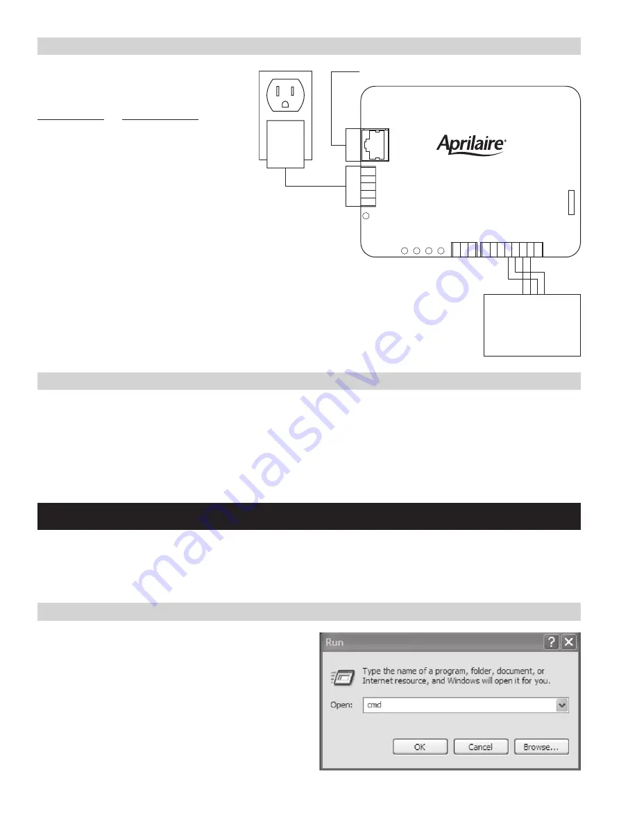
The System Controller connects to the distribution 
panel on the Thermostat port . The wiring is done 
as follows:

 Thermostat  port 

Distribution panel


Pin 4 

B+


Pin 5 

B-


Pin 6 

A+


Pin 7  

A-

There are two methods to connect a computer to the System Controller; directly to a computer (with a crossover Ethernet cable) or using a local 
area network (with a standard Ethernet cable) .
If there is no network available, then the System Controller is connected to a computer using a crossover cable . Plug one end of the crossover 
cable into the System Controller and the other end into the computer’s network port .
If there is a network available, then use a standard Ethernet cable, plugging one end into the System Controller and the other into an available 
Ethernet network jack .

CONFIgURINg THE SySTEM CONTROLLER FOR yOUR NETWORk OR COMpUTER

Once you have completed the installation of the System Controller you are ready to configure the System Controller for use on your network or 
with your computer .
The System Controller is sent from the factory with a default fixed IP address of 192 .168 .0 .100 . If your computer has an IP address that begins 
with 192 .168 .0 then proceed to the System Set-up section . If you don’t know the IP address of your computer, then proceed as follows:

ON WINDOWS COMpUTERS:

1a .  For Windows XP, click on Start, Run to bring up the run dialog 

similar to that shown at the right .

1b .  For Windows Vista and 7, click on Start and then in the Search 

Programs and Files type “run” to bring up the run dialog similar to 
that shown on the right .

POWE

R

LA

N

THERMOSTATS

A-

A+

B-

B+

SYSTEM CONTROLLER

Model 8826

POWER

SUPPLY

APRILAIRE

DISTRIBUTION PANEL

A-

A+

B-

B+

LAN

 – TO LOCAL AREA NETWORK OR COMPUTER

4

Summary of Contents for 8826

Page 1: ...Model 8826 System Controller Model 8826 System Controller Installation Configuration and User Manual READ AND SAVE THESE INSTRUCTIONS...

Page 2: ...at Set up 15 Scheduling 16 Master Schedules 16 Holidays 17 Holds 18 Individual Holds 18 Status 19 Setting Alarms 20 Alarms 21 E mail Alerts 21 Service Reminders 22 Firmware Update 24 LED Diagnostics 2...

Page 3: ...ollowing documents will be useful in installation and setup of a system using Model 8800 thermostats Model 8800 Installation Instructions Document 61000761 Model 8800 Operating Instructions Document 6...

Page 4: ...o the System Controller and the other into an available Ethernet network jack Configuring the System Controller for your Network or Computer Once you have completed the installation of the System Cont...

Page 5: ...n and then go to File and select Properties to bring up the Local Area Connection Properties dialog box on the right below Changing youR IP address If your computer s IP address begins with 192 168 0...

Page 6: ...et Protocol TCP IP Then click Properties to bring up the TCP IP dialogs 3 If the Use the following IP address field is selected make a note of the current IP address and Subnet mask for future referen...

Page 7: ...ntroller or If your computer s IP address does start with 192 168 0 but you want the IP address of the System Controller to be something other than 192 168 0 100 1 Start a web browser on your computer...

Page 8: ...ck to its original setting For Windows XP 1a Start the Control Panel by clicking Start then Settings and Control Panel In the Control Panel locate and double click Network Connections to bring up Netw...

Page 9: ...n dialog box on the right below 2 For Windows 7 select Internet Protocol Version 4 TCP IPv4 or for Windows XP select Internet Protocol TCP IP Then click Properties to bring up the TCP IP dialogs 3 If...

Page 10: ...n out to all the thermostats on the network Number of Thermostats on the network Service Override Temperature Format The number of thermostats on the network can be set either by manually setting the...

Page 11: ...ield is used to select if the equipment controls Cooling in the case of a thermostat or Dehumidification in the case of a humidistat The Fan field is used to select if the thermostat controls the fan...

Page 12: ...et to Off changes to the Mode setting will be allowed to be made at the thermostat The Fan Lock field thermostat only can be set to Full Timed or Off If the Fan Lock field is set to Full changes to th...

Page 13: ...sensor is for Support Module address 1 sensor 2 The third sensor is for Support Module address 2 sensor 1 and the fourth sensor is for Support Module address 2 sensor 2 If a sensor is installed at the...

Page 14: ...to create the User name and password Security can be enabled by setting up a user name and password for both a User and an Administrator The User and Administrator log ins can be created on the Admin...

Page 15: ...rmostat Set up Thermostats are controlled using the Thermostats page The Prior and Next buttons are used to navigate through all the thermostats on the network The Temperature field displays the contr...

Page 16: ...to configure the schedule The Active Schedule can be changed from the individual thermostat schedule to a master schedule using the Active Schedule field Master Schedules The System Controller has fo...

Page 17: ...the Edit Holiday or Daylight Savings Screen the name of holiday being edited appears in the Name field and this field can be modified to change the name of the holiday The holiday to be edited can be...

Page 18: ...e field on the Thermostats page Use the Prior and Next buttons to navigate to the thermostat where the hold will be created The Hold Mode can be set to temporary or permanent In Permanent Hold the Hea...

Page 19: ...le the thermostat is assigned to and the Program column indicates if the schedule is active or if there is an Active Hold at the thermostat The Alarm column will indicate if there are any active alarm...

Page 20: ...until the alarm condition no longer exists For example a sensor value returning to a value above the Low Limit and below the High Limit The Sensors status page displays information for all the sensors...

Page 21: ...Hold ended Date not set Manufacturer initialization occurred EEPROM Failed nonvolatile memory e mail alerts If e mail is set up on the options page alarms will be e mailed out as they occur To set up...

Page 22: ...Reminder and the Service HVAC Reminder field can be used to specify a time period for the Service HVAC reminder The service reminder status can be Disabled Active or Ok The status is Disabled if the r...

Page 23: ...one reminder per season The Service Dehumidifier Reminder field can be used to specify a time period for the Service Dehumidifier reminder The service reminder status can be Disabled Active or Ok The...

Page 24: ...for the System Controller To update firmware on your System Controller go to www aprilairepartners com and download the latest version of firmware and the firmware update utility Once you have downlo...

Page 25: ...rmal Operation LED 2 Ethernet Status Red Solid Unrecoverable Fault Green Flashing Normal operation LED 3 Module Status Red Solid Thermostat Timeouts exist Green Solid Normal operation LED 4 Alarm Stat...

Page 26: ...SULTING FROM ANY BREACH OF THE AFORESAID IMPLIED WARRANTIES OR THE ABOVE LIMITED WARRANTY IS EXPRESSLY EXCLUDED THIS LIMITED WARRANTY IS VOID IF DEFECT S RESULT FROM FAILURE TO HAVE THIS SYSTEM CONTRO...

Page 27: ...ter please make sure it conforms to the following system requirements Supported Operating Systems Windows 7 Service Pack 1 Windows XP Service Pack 3 Supported Web Browsers Internet Explorer 8 or 9 Moz...

Page 28: ...P O Box 1467 Madison WI 53701 1467 Phone 800 334 6011 Fax 608 257 4357 www aprilairepartners com 10009715 1 12 B2205695A Printed in U S A 2012 Aprilaire A division of Research Products Corporation...

Reviews: