background image

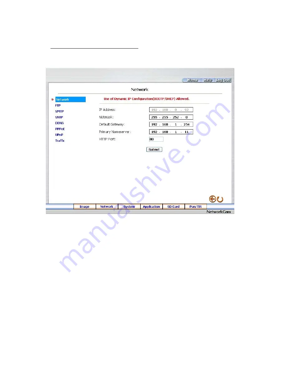
5.1.3  Change the Network Setting 

Please follow the steps below to change the network settings through the network if necessary. 


Set the network options and IP address. 

1. Click the 

Network

 button in the home page to enter the Network page. 


2.  The accessible networks here are the “FTP” (MJPEG mode only), the “SMTP” (MJPEG mode 

only), the “SNTP”, the “DDNS”, the “PPPoE”, the “UpnP” and the “Traffic”. 

3.  Fill in the “IP Address”, “Netmask”, “Default Gateway”, “Primary Nameserver”, and “HTTP Port” 

if necessary. 

4. Click the 

Submit

 button to submit the new network setting. 

5. Click the 

Home

 button to return to the home page. 


29

Summary of Contents for LC-7224EP

Page 1: ...Before trying to connect or operate this product please read this manual completely INSTALLATION OPERATION MANUAL IP CAMERA LC 7224EP ...

Page 2: ......

Page 3: ...CTING WITH A DVR 11 3 3 CONNECTING WITH A MULTIPLEXER 12 3 4 UPDATING SYSTEM SOFTWARE 12 3 5 IP CAMERA SD CARD TROUBLESHOOTING 14 4 Network Configuration 15 4 1 CABLE CONNECTIONS 15 4 1 1 Connect to a computer 15 4 1 2 Connect to a LAN Hub INTRANET 16 4 2 CONFIGURE YOUR IP CAMERA NETWORK SETTINGS 17 4 2 1 Enable DHCP Function 17 4 2 2 Set IP Address 17 4 3 TCP IP COMMUNICATION SOFTWARE 19 4 4 TCP ...

Page 4: ...NS 58 5 2 THE IP CAMERA IP SURVEILLANCE 60 5 2 1 Introduction to IP surveillance 60 5 2 2 Install the IP surveillance in your PC 61 5 2 3 Login the Network camera software 62 5 2 4 Operation 65 5 2 4 The Image Viewer 82 6 ADVANCED OPERATION 83 7 SPECIFICATIONS 88 8 Functions of client PC 89 APPENDIX 1 SCANIP 90 APPENDIX 2 IP Camera UPnP How To 92 APPENDIX 3 The ARP function 102 APPENDIX 4 Register...

Page 5: ...ervice this unit yourself as opening or removing covers may expose you to dangerous voltage or other hazards Please refer all servicing to your distributor retailer Do not use liquid cleaners or aerosols for cleaning To prevent fire or electric shock do not overload wall outlets or extension cord This unit must be grounded to reduce the risk of electric shocks Do not block ventilation openings To ...

Page 6: ...ce makes it easier for you to get your IP address information This unit supports the USB interface which helps you to very easily get an IP address to open the IE browser now just type in your IP address to the browser and you can access your IP camera The device can hopefully provide the advanced motion detection function to improve your network surveillance with both the powerful and enhanced mu...

Page 7: ...le enclosed helps you to set up without a network Camera Digital 24 bit color Image sensor 1 4 inch Sony progressive scan RGB CCD MPEG4 resolution pixels 640 480 320x240 Exposure Automatic AGC White Balance Indoor installation Exposure times 1 30 1 27 000s Sensitivity Minimum Illumination 1 5 Lux F1 2 Image Image frame rate up to 30 frame second Supports two compression modes the Motion JPEG and t...

Page 8: ...air cable 10 100 Mbit Ethernet network connection Modem connection RS 232 modem connector for dial up use Supports most V90 modems Input Output connector to trigger the camera vis a vis external events Operating Environment Operation temperature 41 122 F 5 50 C Humidity 20 80 RHG non condensing WARNING Avoid aiming the camera at the sun or other extremely bright lights Irrespective of whether the ...

Page 9: ...an external control device This port includes ALARM OUT GROUND ALARM IN and ALARM RECOVER for connecting with external devices WARNING You can t use general RS 232 cables to link up with the I O connectors in the rear panel of the device please see the next page for further details 3 VIDEO OUT Connector The connector provides the unit s composite video signals to a monitor 4 Plug Inlet A DC 5V inl...

Page 10: ...ed see the pin configuration chart below for details 4 RS 485 D 5 GND Ground contact 6 ALARM RESET INPUT This pin connects to an alarm clear device for clearing an alarm 5V 20mA 0V Active 7 ALARM IN INPUT This is an alarm input that can be programmed in the menu system to active low 5V 20mA 0V Active 8 ALARM OUT OUTPUT This is an alarm output trigger Connect this to external devices such as buzzer...

Page 11: ...nge the setup of network function enable disable via the network 4 STATIC IP If the switch points down the device can t obtain an IP address from the DHCP server This option is needed to configure the network communication settings 6 POWER Indicator Indicates the power status of the unit The green light indicates the unit is activating The red light indicates the power is on and the SD card cannot...

Page 12: ...ction and ask you what you want to do with your SD card In another words if the user connects the IP camera with an SD card and the PC via the USB connector the IP camera can be used as a normal card reader 2 Remove an SD card As a configuring tool Before using the USB configuration setting page please remember to remove the SD card or your PC will read the SD card and won t show this window Netwo...

Page 13: ...ction between the IP camera and another device If there is no such connection the IP camera factory default Static IP address will not appear on the monitor screen 3 1 CONNECTING WITH AN NVR Use a straight LAN cable to connect directly to an NVR SD Card RS 232 ALARM DC12V AUDIO VIDEO OUT OUT I O RS 485 ETHERNET 10 100 LAN CAMERA CONNECT TO ETHERNET RJ45 CONNECTOR CONNECT TO NVR ETHERNET PORT 3 2 C...

Page 14: ...y 2 Create a directory named IP camera in the SD card if it does not exist 3 Copy the file of UPDATE BIN to the LANCAM directory 4 If the IP camera is running please power it off first 5 Insert the SD CARD into the IP camera 6 Remove the Ethernet cable from the RJ 45 port and then power on the IP camera 7 In 5 to 10 seconds a message reading UPDATE PROCESSING will show up on the screen on a blue b...

Page 15: ...e in step 3 or the IP camera will not work normally after being updated 4 If the power of the IP camera is suddenly lost in step 8 please remove the SD card first and turn on the IP camera next to test its operation If the IP camera remains working normally please go back to step 4 otherwise please inform your technical support 5 In step 10 if the SD card is not removed and the IP camera does not ...

Page 16: ...ort and ignore the following steps 4 Please make sure the function of SD CARD ENABLE is activated in the ALARM and SCHEDULE pages if no cross sign appears beside the SD icon on the screen 5 After recording read the data on the web page of sdget htm If the data cannot be read through the network please read it instead in a PC check the data stored in the LANCAM directory and contact your technical ...

Page 17: ...ion for connections Physical specifications of the RJ 45 cable for Ethernet Wire Type Cat 5 Connector Type RJ 45 Max Cable Length 100 m Hub Wiring Configuration Straight Through PC Wiring Configuration Straight 4 1 1 Connect to a computer Use a straight LAN cable to connect directly to a computer RJ 45 CROSSOVER CABLE CROSSOVER CABLE PIN CONFIGURATION LAN CAMERA TO PC LAN CARD 15 ...

Page 18: ...4 1 2 Connect to a LAN Hub INTRANET The RJ 45 PIN configuration for connecting with a LAN Hub is shown below RJ 45 LAN CAMERA TO PC NETWORK CARD uplink 16 ...

Page 19: ...HCP server Otherwise please follow the instructions given below Set the IP MASK and GATEWAY The following is a sample setting IP 192 168 1 X MASK 255 255 255 0 GATEWAY 0 0 0 0 NOTE When only one unit of the IP camera is connected to a computer or LAN you can freely assign an IP address for the IP camera For example there is a range of IP camera IP addresses from 192 168 1 1 to 192 168 1 255 You ca...

Page 20: ...ork is identified as Class C for example the first three sets of numbers of the IP camera IP address must be the same as the network address If the connected network is identified as Class B the first two sets of numbers of the IP camera IP address must be the same as the network address If you have any questions regarding these settings please consult a qualified MIS professional or your ISP 18 ...

Page 21: ...ftware Follow the procedure below to install the TCP IP communication program in your computer Click the Start menu from your computer and point to the Settings Control Panel Double click the Network icon to enter the windows 19 ...

Page 22: ...components list If the TCP IP is included please process section 4 5 If it is not included please follow section 4 4 to install the TCP IP 4 4 TCP IP Installation During the installation you will be requested to insert the Windows CD ROM After installation the PC may be restarted 20 ...

Page 23: ...erver please select Obtain an IP address automatically Any assigned IP address for the connected IP cameras must be in the same class type as the server If there is no DHCP server please select specify an IP address and type in the IP address of your PC This IP address must be different from other network IP devices but in the same class type NOTE The IP address of an IP camera in a network must b...

Page 24: ...blished the connection successfully Click Start Programs MS DOS Prompt Type in ping 192 168 1 168 then enter See the sample screen below This IP is the IP camera IP address that is assigned for the connected IP camera in step2 If you receive a response as in the sample screen below the connection hasn t been 22 ...

Page 25: ...hardware and software installations by repeating steps 1 to 5 If you still can t establish the connection after rechecking please contact your dealer If you receive a response as in the sample screen below you have successfully made the connection 23 ...

Page 26: ...or watching recorded data through the TCP IP protocol The details are listed as follows RJ 45 PIN configuration for Ethernet PIN NO PIN Assignment 1 TX 2 TX 3 RX 4 Not Connected 5 Not Connected 6 RX 7 Not Connected 8 Not Connected RJ 45 socket 1 2 3 4 5 6 7 8 Physical specification for Ethernet Wire type Cat 5 Connector type RJ 45 Max cable length 100 m Hub wiring configuration Straight Through or...

Page 27: ...es 6 Click the OK button to set your entries and automatically exit the page NOTE The default User Name and Password are admin and 9999 respectively NOTE The page headlined Enter Network Password is shown below Please enter the user name and password of the IP camera when you see it If either the user name or the password is incorrect please check the input data and rectify it if necessary NOTE On...

Page 28: ...RD window if the SD card is inserted Click the Pan Tilt button to change the Pan Tilt Zoom settings Click the button to change the time date display mode Click the button to switch high low speed network Click the button to play the live audio Click once again to deactivate Click the button to archive AVI videos into your PC Click once again to deactivate In the recording mode there will appear a ...

Page 29: ...st the image setting including Device Title Resolution Quality Frame rate MPEG4 mode only Format and Viewer Type MJPEG mode only if necessary 3 Click the Submit button to submit the new image setting 4 Click the Fine Tune button to enter the Image Fine Tune page to set the details of the device including Brightness Saturation and Sense Up Click the Default button to reset all the settings NOTE The...

Page 30: ... to choose the image quality out of a spectrum of qualities ranging from highest high medium and low to lowest In MPEG4 mode you can also set the quality by typing in the value The custom quality value must be in the range between 64 Kbps to 8192 Kbps Frame rate Click the drop down list to choose the frame rates of 5FPS 10FPS 15FPS 24FPS or 25FPS Brightness Enter your desired quality of image brig...

Page 31: ...on in the home page to enter the Network page 2 The accessible networks here are the FTP MJPEG mode only the SMTP MJPEG mode only the SNTP the DDNS the PPPoE the UpnP and the Traffic 3 Fill in the IP Address Netmask Default Gateway Primary Nameserver and HTTP Port if necessary 4 Click the Submit button to submit the new network setting 5 Click the Home button to return to the home page 29 ...

Page 32: ...and 255 It is used to identify the subnet where the Network camera is sited Default Gateway Type in the 4 byte Gateway in the relevant blank space each unit value must be between 0 and 255 Primary Nameserver Enter the 4 byte DNS Server Address in the blank space provided each value unit must be between 0 and 255 The DNS Server is in charge of translating the Domain Name into the IP Address HTTP Po...

Page 33: ...it button to submit the new FTP setting of the recording 4 Click the Home button to return to the home page Description of function keys FTP IP Address Enter the FTP server DOMAIN NAME in the appropriate blank space User Name Fill in the FTP login user name in the attached blank space if the data is not provided warning messages will show up Password Type in the FTP login password in the attached ...

Page 34: ...r name DOMAIN NAME of the SMTP server and set the recipient s e mail address if necessary 4 Click the Submit button to submit the new SMTP setting 5 Click the Home button to return to the home page Description of function keys Account Name Password Fill in the account name and password if you check marked the My Server Requires Authentication function SMTP Server Enter the SMTP server DOMAIN NAME ...

Page 35: ...r Daylight Saving Time Changes to checkmark the attached box and activate the function 4 Click the Submit button to submit the new SNTP setting 5 Click the Home button to return to the home page Description of function keys SNTP Server Enter the SNTP server DOMAIN NAME in the blank space provided Time Zone As we know the globe is divided into various time zones The user must enter his her time zon...

Page 36: ... open the list of three DDNS modes to choose from DynDNS hn and adsldns Click the Apply button and connect their website automatically and visit it Type in your dynamic IP Address and Email Address If they are accepted by the website you will get an Email containing your DDNS Account and DDNS Password in your Email box 4 Type in the DDNS Host Name the DDNS Account and the DDNS Password 5 Click the...

Page 37: ...on and connect this website automatically and enter it Type in your dynamic IP Address and Email Address If they are accepted by the website you will get an Email containing your DDNS Account and DDNS Password in your Email box DDNS Host Name Type in your host name in the attached space DDNS Account Enter it in the given space DDNS Password Enter it in the required space Submit Click to set 35 ...

Page 38: ...ng document first then press Close button 3 Click the PPPoE mode to activate the function 4 Type in the PPPoE Account and the PPPoE Password 5 Click the Submit button to submit the new setting 6 Click the Home button to return to the home page NOTE Please refer to section 5 1 8 PPPoE DDNS for more details Description of function keys PPPoE mode Click your choices to enable the PPPoE function Accou...

Page 39: ...e UPnp Max Expired Age the SSDP Port and the UpnP Port 4 Click Enable UpnP Memory Card Access to checkmark the attached box and activate the function 5 Click the Submit button to submit the new setting 6 Click the Home button to return to the home page Description of function keys Max Expired Age Enter it in the given space from a range of 10 3600 SSDP Port SSDP stands for Simple Service Discovery...

Page 40: ...e to enter the Network Traffic page 2 Type in the Maximum Upload Bandwidth and the Maximum Download Band d wi th 3 Click the Submit button to submit the new setting 4 Click the Home button to return to the home page Description of function keys nter it in the given space from a range of 0 to 102400 400 Maximum Upload Bandwidth E Maximum Download Bandwidth Enter it in the required space from a rang...

Page 41: ...nually Synchronize With Computer Time and Synchronize With SNTP Server 3 Click the 4 Click the Home button to return to the home page Description of function keys The Local Time Shows the current date and time of the Network camera uter ode two choices of Su ubmit the new setting to the Network camera Set Manually Manually sets the date and time of the Network camera Synchronize With Computer Time...

Page 42: ...r s settings 4 Click the Home button to return to the home page Description of function keys User List The list shows the registered user s and the corresponding authority Delete Deletes a selected user Name Enter the user s name which will be added or modified Password Enter the new password of the user s name above Confirm Type in the password again for verification Authority Choose an authority...

Page 43: ...o enter the Digital I O 2 Mark the Digital Input ON or OFF and the Digital Output ON or OFF Click your choices to enable ubmit the new user s settings 4 3 Click the Submit button to s Click the Home button to return to the home page De Dig wn Dig nector or deactivate it scription of function keys ital Input Select ON or OFF to use the GPIO connector or shut it do ital Output Select ON or OFF to us...

Page 44: ... Aud Mechanism Set 2 Mark the Audio Mechanism ON or OFF 3 Click the Submit button to submit the new user s settings 4 Click the Home button to return to the home p ge ve audio service is only provided in the MPEG4 mode via the Web browser a NOTE This setting is for turning the audio mechanism of the Camera on off automatically The Li De ion keys or OFF to activate or deactivate the function script...

Page 45: ...e RS232 Setting page Description of function keys Baud rate Eight different speeds can be used 2400 baud per second 4800 baud 9600 baud Ty Raw format Set to transmit the ASCII codes ransmit the character string 19200 baud 28800 baud 38400 baud 57600 baud and 115200 baud pe Choose one of the types Canonical format Set to t 43 ...

Page 46: ...tion keys s can be used 2400 baud per second 4800 baud 9600 baud Type Cho f using an ID code any number between 1 and 255 Baud rate Eight different speed 19200 baud 28800 baud 38400 baud 57600 baud and 115200 baud ose one of the types Device ID You have the option o Raw format Set to transmit the ASCII codes Canonical format Set to transmit the character string 44 ...

Page 47: ...ary 1 Cl Click the Browse button to select the UPDATE BIN file which was copied into your computer 3 4 Note ile the unit is updating itself Note is fit in with the model of the unit Updating sical damage to the device 2 Click the Update button DO NOT power off the Network camera while this update process is running Don t interrupt the process wh Please make sure that the UPDATE BIN file with the w...

Page 48: ...per left above to enter the Event Log page 2 Choose one of the three buttons shown on the page to view an event when necessary The three buttons are titled First Page Previous 20 and Next 20 Description of function keys First Page Displays the first page Previous 20 Displays the previous 20 pages Next 20 Displays the next 20 pages 46 ...

Page 49: ...n Setting page default in the required number of images you wish to set in Pre Alarm y Buffer respectively in their corresponding blank spaces 3 4 e entries for their settings 5 Click the Home button to return to the home page 2 For the storage setting type Memory Buffer and Alarm Memor Enter the Upload Rate you have chosen Click Submit after each of the abov Description of function keys Pre Alarm...

Page 50: ...ng data live 1 Click the SD card button on the top left to enter the SD Card Application Setting page Description of function keys MJPEG Format One image per file MJPEG Continuous Mode The continuous recording mode of MJPEG compression Max MJPEG Numbers Sets the number of file sequences you can save per second AVI Format audio setting Unlike a single image file this option offers a selected sectio...

Page 51: ...browse to select ting and ending triangle to Download SD Utility You also can click Download SD Utility to SD Card to backup the so y a S Execute th SDCut Insert an computer Click the SrcDir button to bro recorded files stored in the LANCAM directory of the SD card as shown in Figure B Step 3 Select the exporting path Specify the file p picture Click the DesDir button the path for the single pictu...

Page 52: ... SMTP button on the left side to enter the SMTP Application Setting page sary The maximum number which can be submit the new SMTP setting of the recording Click the Home button to return to the home page 2 Enter the attached file number as and when neces used is 8 3 Click the Submit button to 4 Description of function keys File numbers Sets the quantity of images per Email ...

Page 53: ...ow to change the Language setting via the network if necessary 1 Click the Language button on the left side to enter the Language Setting page elected language and click Submit to set it 2 You have an option as to which language to use The default is English 3 Click your s 51 ...

Page 54: ...he attached box and activate the function 4 Click the Submit button to submit the new setting of the recording Please follow the steps below to change the setting via the network if necessary 1 Click the Enable Record button on the left side of the record to enter the Record 5 Click the Home button to return to the home page Description of function keys Enable Record Upload Via FTP Activates or de...

Page 55: ...lear out all the data of the schedule setting item while it is enabled 3 Click the Submit button to submit the new schedule 4 Description of function keys Schedule Check uncheck the first seven boxes in a vertical row on the left to enable disable the programmed scheduled recording function if necessary Vary any of the schedules of the recording setting if necessary please refer to the above descr...

Page 56: ...ease follow the steps below to change the setting via the network if necessary function 5 Click Enable Alarm Upload Via SMTP to checkmark the attached box and activate the function MJPEG mod 6 Enter the Alarm Duration you have chosen the 8 Click the Home button to return to the home page Description of function keys Enable Activates or deactivates the alarm ALARM Trigger an Alarm When Ethernet Is ...

Page 57: ... setting of the recording image coordinates provided below NOTE You can set more than 3 Click the right mouse button to see the popup Save setting 4 Enables disables the motion detection function 5 6 Click the Submit button to s 7 Click the Home button to return to the home page Description of function keys The targeted zone Click and drag the mouse across the targeted zone to draw a red rectangle...

Page 58: ...to display the images therein 3 Each file can be deleted by clicking the attached DELETE hyperlink k SAVE to save the file computer you can enter ARD page to click in and enter the Move your m in the image area and click the right button of the mouse A and select the path by which to save your NOTE You can t directly click the hyperlink of the file in the FILELIST of MEMORY CARD page with the righ...

Page 59: ...cting port The RS 232 communication port functions as a connector to an o Upon the buttons being clicked a camera will move one short step only in any of the four 6 Click button 7 Click to zoo 8 Upon the buttons being clicked a camera will turn all the way without stopping in one of the four designated directions Click the buttons to control the Aperture setting on the Speed Dome Controller Each o...

Page 60: ...and select the configuration Select the TCP IP Choose the properties Type in the IP address in a four part formula for example identical to the above numbers only the last part can be changed to your own number which must never exceed 255 Click the mask and the mask input namely 255 255 255 0 fixed formula Click OK Click OK 5 Desktop Choose IE browser Type in the IP camera IP address in the URL c ...

Page 61: ...NS is just for your convenience NS settings Check your IP camera s I Use the address to connect to the LAN CAM or view the image Type in User name admin and Password Choose the DDNS Click Enable DDNS Enter the DDNS host name for example abc123 homeip net Type in DDNS Account for example abc123 Enter the DNS Password for example 7777 Submit The settings are now complete Close the IE browser Open th...

Page 62: ... LAN WAN Now enter the main menu to set the IP address 5 2 The IP camera I This section provides instructions for ins which are included with the IP camera The programs can be operated by a selected PC equipped with the following requirements S Intel Penti 128 MB RAM at least 256 MB or higher recommended Windows 2000 XP or above 4 MB VGA card capable of 24 bit true color display 100 MB free hard d...

Page 63: ...stall the IP surveillance from the supported CD R 1 Exit all applications currently running in the selected PC automatically Follo procedure as they appear NOTE It will update the NET Framework to version 2 0 aut to continue to Programs IP surveillance IP surveillance to open up the program selection page as shown below Click the IP surveillance tag to start the IP surveillance program Install the...

Page 64: ...r will me admin and the password 9999 in the respective sp button and enter the console page of the IP surveillance both the user name and sword must be entered corre work Viewer View work camera video from a remote PC Follow the instructions below to use the IP surveillance to browse a Network camera video fr follo the Net om a remote location Upon entering the IP surveillance a connection box wi...

Page 65: ...ct at the bottom of the page to access the Connect Network camera Wizard page again 2 Type in the IP Address or the domain name and HTTP port of the device and add the device to the Device List 5 Type in the Password in the Connect Network camera Wizard page Click Next button to open another Add Device Wizard page Wizard page to discover the connection of the Network camera type device in the LAN ...

Page 66: ...t Mode NOTE Please click the icon to see the details of the Connect Mode to 7 After finishing the setting of the Device Recording please click the Finish button establish the connection between the device and the computer 8 Click the devise title to begin viewing images with this camera from the Device List NOTE To add more connections or units to the Network camera please repeat the above instruc...

Page 67: ...ick on the title of the camera that was connected 2 Hold down the right mouse button and drag onto the droppable Live Monitor area The video from the new camera will be displayed 3 In the Live Monitor area if you want to exchange the videos of different cameras ti format screens 3 The Sequence configuring button Press to enter the sequential jumping mode each you can drag the video and drop it whe...

Page 68: ... to show a window You can select Delete Capture Print Play Stop Audio or Reexamine Audio Mechanism 9 Click this button to hide the devices list common and alarm message list boxes from view behind the video display screen 10 The section in the upper left margin will show the information in all the devices and its st and drag it to the Live monitor channels accordin video and drop it as s he likes ...

Page 69: ...era which you want to delete 2 Press and hold the left mouse button Then drag it to the trashcan and release the mouse button 12 Alarm list PTZ Control Shows the alarm types the device names and the occurrence time You can press the PTZ button to change to the PTZ Control mode 67 ...

Page 70: ...to enter the Playback Viewer setting page 1 The Playback Viewer icon 2 The display area 3 Click to choose the Recording List Live Event Message Click The alarm events which were recorded will be marked in pink color to refresh the recording list ...

Page 71: ... This box allows you to access all recorded video which are ed devices stored in the HDD of the connect 6 Playback function bar Play Click to a recorded video from the PLAY LIST Stop Click to stop playing back a recorded video or cease recording Pause Click to freeze the image Step Click to view images picture by picture Zoom in Enlarges the displayed image Zoom out Narrows the displayed image Cap...

Page 72: ...a sequence of images in a file Warning The audio and video signals would likely be unable to play back ed by unstable network transmission or udio function ar to search the video You can want to see 12 Press the simultaneously because of incomplete files caus altered setup while doing the AVI backup with the Include A 10 Scroll bar for video searching Drag the square on the b click or pull the ind...

Page 73: ... press OK to save it Remove a device group Click then press this button and select the group name OK to delete the group Add a new camera For mode details please refer to section 5 2 3 Remove a camera Click this button and select the group name and Network camera then OK to delete the device To edit camera Please select a device then click this button to edit the device ...

Page 74: ...s you can click the Device Setting button opening a Device Setting screen and set the settings of the Device page where you can change the Audio Mechanism function to OFF Turning it OFF will save the bandwidth from wastage and improve the image display 3 Alarm Setting page 4 SD card Setting page NOTE Please remember to click the Apply button to save the settings System Setting Provides six pages o...

Page 75: ...ntage on five levels Default Directory Sets the default files saving path Click to select the directory 2 Event Notification Channel Prompt Sets each camera to activate or deactivate the three modes of Motion Buzzer Alarm Focus Tick mark Sensor Buzzer and the blank space for each device to activate it 73 ...

Page 76: ...device to activate it Popup Message E mail Notice Sets each camera to activate the E mail Notice function of the three each device to activate it situations Motion Alarm Sensor Alarm and DISK Full Set the SMTP the E mail address and the attached file numbers to mail the user when the alarms occur Tick mark the blank space for ...

Page 77: ... HDD reserved space by using the scroll bar Recording quota setting Set the maximum recording quota of each channel 4 Scheduler 1 Choose one of the devices to set its recording schedule 2 Select the period Click to set to record only once or record every day 75 ...

Page 78: ...e You can also use the right mouse button to cancel the period 4 Select the recording mode 5 Press to show the scheduled recording list 6 Set the secondary schedule Activate or inactivate the other recording modes besides the primary schedule Option buttons editing area Save Apply the changes Close Close the window 5 Sequence Views 7 Undo Undo the latest changes Clear Clear all the schedule marker...

Page 79: ...how in the Location Setting area Step 3 r channels Location1 4 then click the Setting button will show below Choose the device s and set the Dwell ist then press the Confirm button Select one of the fou Step 4 The 4 SEQ View s page Time 3 30seconds from the drop down l Step 5 Set the other channels as in step 3 4 button then press Close button to exit the setting page Step 6 Click Save all Step 7 ...

Page 80: ...elected channel The user can set the model ID and the protocol here Click Configure to enter to the RS232 and RS485 setting pages 7 Authority Setup 78 Authority setup Change or add the user s authority There are three different levels of authority namely Admin Operator and Viewer ...

Page 81: ...g mode and click the Config Record button to set the details of the recording below e Device Panel and Web page The web page please refer to section 5 1 for more details 8 Status of the speed dome controller 9 You can interchange between two buttons here th buttons 10 Device information The user can read a camera s information such as Site Name Group Name IP Address HTTP Port Device type Monitor A...

Page 82: ...een next to the time display 5 2 4 5 Logout Press the on the taskbar and is commonly in the bottom right hand corner of the button to logout the IP Surveillance software and the IP Surveillance monitor will be minimized into the systray of the Windows taskbar If you want to return to the IP Surveillance monitor please click the button once then select the page which you want to get into After typi...

Page 83: ...nimized into the systray of the Windows taskbar Click the button to select the functions on the list You can also change the password by clicking the Tools and Change password items on the list Enter the old password once and the new password twice then press the OK button to save it 81 ...

Page 84: ...urveillance Tools to open up the program selection page Click the Image Viewer tag to start the Image Viewer program see a sample screen below 2 Click the RELOAD tag to load the images from a path 3 Click the PRINT tag to get a displayed image printed out from a printer 5 2 4 The Image Vie The rk camera is equipped with a digital watermark It s a checking softw which protects archived images and i...

Page 85: ...rom Lowest Low Medium and High to Highest 6 Click the Submit button to submit the setting Recording the images into an SD card while the motion detection function is working 1 Click the application button in the home page 2 Click the Enable button below the ALARM item on the left side of the page to enter the tion 1 o view the live images of the IP camera via the Microsoft Internet Explorer on the...

Page 86: ...ed in 4 Click the S NOTE Please remember to insert the SD card into the built in SD slot of the unit first Set the recording time the AVI duration of the SD card 1 Click th 2 Choose the AVI Duration from the drop down list If you want to record the file into the SD card for 30 seconds please choos 3 Click the Submit button to submit the Use IE to view the recorded files 3 It will ask y 4 If you di...

Page 87: ... in the home page SETTING page 3 Choose ON from the PPPoE mode list to activate it 4 Enter the Ac 5 Click the Submit button to submit the setting NOTE Please refer to section 5 1 8 for more details 1 Click the URL block at the t 2 Type in the DDNS Host Name of the IP camera into the URL block and press the Enter button to 3 Enter the user name and fill in the pa 4 Click the OK button and enter the...

Page 88: ... k the application button ck the FTP button on the left side of the page to enter the FTP APPLIC TTING page t the last item Upload Rate at the bottom of the page t The FTP function is not provided in the MPEG4 mod or modify the users and their authorities of using the IP camera ntering the sett Click the system button in the home page Users button on the left side of the page to enter the SY Pleas...

Page 89: ...y on the User List Enter the password the confirmed passwor 2 d and choose the authority Delete a user you want to modify on the User List 3 Click the Submit button to submit the new setting 1 Click the user name 2 Click the Delete button 87 ...

Page 90: ...n Advanced MD zone position sensitivity MPEG4 Resolution VGA QVGA MPEG4 Quality 5 Levels Bitrate from 3Mbps to 128Kbps MPEG4 Framerate 25 24 15 10 5 fps at all resolutions Video fine tune Brightness Saturation RS 232 Yes Network Interface Ethernet RJ 45Wired 10 100 Base TX MDIX Support Network Protocol TCP IP DHCP HTTP UDP FTP SMTP SNTP ICMP DDNS DNS UPnP SD socket Yes Alarm I O Yes Secure passwor...

Page 91: ...ystem require Browser IE 6 x Live Monitor Max 16 Split Real Time Event Full Screen REC Capture Audio Live Playback Viewer Playback Time live event Sea JPEG AVI rch Export Settings Device System Camera ma age nagement web p Multi camera link Max 16 camera 89 ...

Page 92: ...vice from the Device Type 3 Click the desired device to show the window while the IP camera information acts to display the desired changes instantly Th will display the connection of the all type device 4 Do you want to manually set the IP i If you want to manually set the IP of the device please select the desired device from the Device Type then click the button ii The software will provide the...

Page 93: ...ddress box on the right as well as the device s login Account and Password in their respective blanks at bottom left then click Submit and the new address will automatically be sent to the device v Click Exit at bottom right to shut the device Link to the homepage of the selected device Select the desired device from the Device Type then click the 5 button to connect to the homepage of the device ...

Page 94: ...own in Figure1 below yo Figure 1 UPnP Setup Flow Chart 1 Check the IP class of your PC In most case Microsoft Windows XP will assign an IP address 169 254 automatically with a subnet mask 255 255 0 0 if the Camera There won t be any ferent IP class domains and you have to modify the relative settings or protocol won t work however checking your own IP address is necessary Here are the procedures t...

Page 95: ... Network Connections dialog box appears See Figure 3 Figure 3 Step 3 Click the Protocols tab in the Network Connections dialog box See Figure 4 Figure 4 Step 4 When the Local Area Connection Properties dialog box shows up choose Internet Protocol TCP IP and click Properties See Figure 5 93 ...

Page 96: ...x choose Use the following IP Address to indicate that you do not wish to use DHCP and assign IP Address 192 168 1 200 with Subnet mask 255 255 255 0 Click OK when you finish it See Figure 6 Figure 6 Step 6 Choose Close to finish the modification See Figure 7 Figure7 94 ...

Page 97: ... steps will help you to install them Step1 From the Start menu point to Set Program Access and Default and then click it See Figure 8 Figure 8 Step 2 When the Add or Remove Programs dialog box appears click the Add Remove Windows Components button See Figure 9 Figure 9 Step 3 Check the Network Services in the Windows Component Wizard dialog box and then click Details See Figure10 95 ...

Page 98: ...Figure 10 Step 4 Check UPnP User Interface and choose OK See Figure 11 Figure 11 Step 5 When the original Network Component Wizard dialog box returns click Next See Figure12 Figure 12 96 ...

Page 99: ...n we should turn on the relative services to start the UPnP protocol The following procedures will teach you how to do it Step 1 From the Start menu point to Settings and then click Control Panel See Figure14 Figure 14 Step 2 When Control Panel appears double click the Administrative Tools icon The Administrative Tools dialog box appears See Figure15 97 ...

Page 100: ...ure15 Step 3 Click the Services icon in the Administrative Tools dialog box 6 See Figure1 Figure16 Step 4 When the Services dialog box shows up double click the SSDP Discovery Service icon See Figure17 98 ...

Page 101: ...ep 5 Choose Automatic in the Startup type and click OK to start it See Figure18 Figure18 Step 6 log box appears again double click the Universal Plug and Play Device Host icon See Figure19 When the Services dia 99 ...

Page 102: ...Figure19 Step 7 Choose Automatic in the Startup type press the Start button and click OK to start it See Figure20 Figure20 Step 8 Restart your system 100 ...

Page 103: ...e UPnP protocol will take effect You can scan all IP Cameras in My Network Place like Figure21 and Figure22 below Figure21 Figure22 Just double click the UPnP IP Camera icon and the video live stream will pop up automatically without assigning any IP address in Microsoft Internet Explorer 101 ...

Page 104: ...mmand Use any of the following ways to set the IP address within thirty seconds after booting the IP Camera re cycle the power Setting IP using the method below can only be done on the Ethernet interface ARP and ping from Windows or MS DOS The user can open the PC s MS DOS windows from the WINDOWS 98 operation system or open the PC s Command Prompt windows from either the WINDOWS 2000 or the WINDO...

Page 105: ...rd after the reset are admin and 9999 1 2 Type the following as superuser root arp s IP address Ethernet address or arp s IP address MAC address ping IP address Example arp s 192 168 1 100 00 0C 0C 00 00 01 ping 1 The device responds to the ping in the exampl this method will set the IP address permanently Note The default a 103 ...

Page 106: ...in Figure 1 Figure 1 Create an account After clicking Create Account you will enter the Create Account page Please complete the form at the bottom of the page to create your account You will receive an e mail containing instructions to activate your account If you do not follow the directions within 48 hours you will need to recreate your account Set up the DDNS After creating the account successf...

Page 107: ...he My Hosts item as shown in Figure 4 Click Add Host Service and its service items will appear The Add Dynamic DNS Host add a new DDNS Each member may have only one free account and one item helps to free account can have only five DDNS Click Add Dynamic DNS Host to enter the DDNS setting page as shown in Figure 5 105 ...

Page 108: ...st button as shown in Figure 5 All we have to set in this page is the Hostname item The user can choose a Sub Hostname as s he likes from the right hand side of the Hostname s drop down list NOTE You don t have to set the IP Address in the same Address It will renew the IP Address automatically 106 ...

Page 109: ...Figure 6 107 ...

Page 110: ...75 1 31 0 88 QVGA 0 66 0 56 0 44 0 38 0 22 ZOOM 2 3 2 5 2 1 5 1 ZOOM 3 3 2 5 2 1 5 1 ZOOM 4 3 2 5 2 1 5 1 2 When frame rate is lower or equal to 15 ond Highest High Medium Low Lowest frames sec VGA 1 94 1 69 1 31 0 98 0 66 QVGA 0 5 0 44 0 34 0 25 0 19 ZOOM 2 2 25 1 88 1 5 1 125 0 75 ZOOM 3 2 25 1 88 1 5 1 125 0 75 ZOOM 4 2 25 1 88 1 5 1 125 0 75 The unit is in Mbps second ...

Page 111: ... off on the IP camera A Visit the homepage tailpage htm of the device and select ON or OFF in the OSD column Example suppose the IP address of the device is 192 168 1 168 Type in http 192 168 1 168 tailpage htm rn IP SWIT from o 4 and c ge the ative netw Addres sk and ay on the image ge 2 Can the S ard ed du A No it cannot be removed unt flashing light als the SD card is operating Th red light w c...

Reviews: