background image

Unpacking

Preparation

Installation

Warranty

Operation

Appendix

Overview


REV-3.0 [3-17-11]


10

ComCenter-II ‘Outdoor’ 

Product Manual 

Installation

Installation

 (continued)

The next steps in the installation process involve making all of the final cable connections and mounting the 

ComCenter Outdoor Device to the newly assembled mounting bracket.

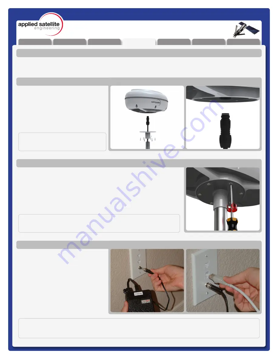
Plug the Female end of the communications 

cable  to  the  underside  of  the  ComCenter 

Outdoor unit.  The cable is “keyed” to allow 

proper pin alignment, gently rotate the plug 

until it slides into place with a tactile “click”.

Attaching Cable to ComCenter

Once aligned, tighten the mounting screws in the bracket to the underside of the 

ComCenter Outdoor Unit.

Attaching ComCenter to Bracket

Now  that  the  device  is  fully  installed,  plug 

in  the  standard  telephone  handset,  the 

CAT-5  Communications  Cable,  and  finally 

the power Supply Cable as shown.  Confirm 

(again)  proper  connectivity  by  listening  for 

the tone patterns in the handset.

If you do NOT have a steady dial tone, you 

should  first  check  all  of  your  connections 

and try again. 

Attaching Power and Phones to Wall Plate

NOTE:

At this point, you should be able to pick up the Handset and hear a steady Dial Tone.  If not, see troubleshooting 

in Appendix A

IMPORTANT: 

Be careful not to bend pins.

IMPORTANT: 

The ComCenter Outdoor must be installed and oriented horizontally as shown 

for proper satellite visibility.

Summary of Contents for ComCenter-II 'Outdoor'

Page 1: ...outing Cables 9 Connecting the ComCenter 9 Attaching Cable to ComCenter 10 Attaching ComCenter to Bracket 10 Attaching Power and Phones to Wall Plate 10 Operation 11 Typical Start Up Sequence Overview 11 Power On Confirmation 11 Ready For Use Confirmation 11 Connecting To Your Computer Or Network Via Ethernet 12 Changing Modes 12 Finding your ComCenter With ASE Device Manager 13 Changing the Ether...

Page 2: ...ctions up to 3Km Special tone sequences indicate normal and adverse conditions SmartDial Dialing Sequence Data Features Data Connectivity using Ethernet Infrastructure AT Commands for direct modem control Port forwarding for IP based control of remote equipment Administrative Features A PC Based user console for system setup and status Captain Crew PIN Codes assignments for multi user authorizatio...

Page 3: ...eport 86 Department of Health and Welfare Canada Safety Code 6 These standards are based on extensive scientific review For example over 120 scientists engineers and physicians from universities government health agencies and industry reviewed the available body of research to develop the updated ANSI standard The design of your phone complies with these standards when used as described under Unit...

Page 4: ...ing Areas To avoid interfering with blasting operations turn your unit OFF when in a blasting area or in areas posted Turn off two way radio Obey all signs and instructions 11 Potentially Explosive Atmospheres Turn your unit OFF and disconnect the power supply when you are in any area with a potentially explosive atmosphere Obey all signs and instructions Sparks from your battery or power source i...

Page 5: ...em Users If using the ComCenter with a PABX system the following precautions must be followed to prevent damage to your unit The ComCenter emulates a standard land line wall jack and generates the required operating and ringing voltages Connect to a PABX as either a central office CO or trunk line Never connect the ComCenter to a PABX as an extension or damage to the PABX or ComCenter may result ...

Page 6: ...ponent will vary widely For this installation you will need a safe work area that is outdoors with a 360 degree view of the sky for device testing along with a few tools including a 2 Phillips screwdriver a 2mm Allen Wrench and possibly a stable Ladder Tools Required for Installation A ComCenter IIG Outdoor Unit B Communications Cable C Universal Wallplate D AC DC power adapter Universal AC input ...

Page 7: ...en installed close the SIM door and lock it with the provided screws Next re attach the top shell taking care that the waterproof gasket seals properly as shown Screw down the casing fasteners only once the gasket is properly seated Re Assembling ComCenter Casing IMPORTANT Be sure that the rubber seal is properly seated before re tightening the Casing Screws NOTE This device will be shipped to the...

Page 8: ...ustration If you prefer to connect the system to another DC power source then simply separate the wires as shown in the bottom illustration and connect those to the alternate source Next connect a standard analog POTS telephone into the RJ11 jack 24 36VDC 15 Watts Attaching Phone and Power Once the initialization has completed about 30 seconds you should hear one of the following tone patterns dep...

Page 9: ...n Attaching Bracket to Pole Feed the Communications cable down the bracket and pipe toward your designated communications area It is important to leave yourself 6 8 of extra cable that will serve as a service loop while attaching the ComCenter Outdoor Unit Routing Cables Pull the opposite end of the communications cable through the wall and attach it to the supplied wall plate adapter Next attach ...

Page 10: ...ligned tighten the mounting screws in the bracket to the underside of the ComCenter Outdoor Unit Attaching ComCenter to Bracket Now that the device is fully installed plug in the standard telephone handset the CAT 5 Communications Cable and finally the power Supply Cable as shown Confirm again proper connectivity by listening for the tone patterns in the handset If you do NOT have a steady dial to...

Page 11: ...ter power up you should hear a tone pattern through the standard telephone handset this indicates that the system is searching for the Iridium network Long Short Searching for Network Registered with Network Standard Telephone Handset Once the ComCenter has established a network connection to the Iridium Satellite Network you will then hear the following Short Short Short Short Short Found Home Ne...

Page 12: ...P CLIENT MODE For single node or networks with fixed IP addresses The direct mode allows you to manually assign a fixed IP address to the ComCenter II The ComCenter II s default IP address is 192 168 1 100 but can be changed if needed Direct mode is typically for advanced users who need to assign specific IP addresses to support their network configuration DIRECT MODE CONNECTING TO YOUR COMPUTER O...

Page 13: ...on CD ROM Install on your host computer and let the ASE Device Manager simplify your network installation Simply click the FIND button and the ASE Device Manager will scan your network for ASE Devices Found device s will then be listed in the drop down Profile box You can now select the device from the profile box and open its unique webpage to access its data features or connect your PC to the In...

Page 14: ... POTS RJ 11 Changing the Ethernet Connection Mode Using POTS RJ 11 994 gives audible beeps according to mode setting Accessing the embedded webpage in the ComCenter II may not be possible unless the default DHCP Client mode is compatible with your specific network Once you are able to access the ComCenter II s webpage the mode can be changed by clicking on the CONFIGURE button This page will allow...

Page 15: ...re using Changeable settings include SmartDial 911 USA Crew ID protected access Captain s card installed Periodic reporting PBX Answer Signaling Voice volume adjust POTS RJ11 access only Event log and diagnostic monitoring embedded webpage only Restore to factory defaults The embedded webpage provides simple selection and dialog boxes for easy setting changes Many of these settings can also be acc...

Page 16: ...rides SmartDial recognition of country codes and allows United States callers to simply type 911 to access the emergency system If this setting is off then calls starting with 91 are recognized as dialing the country code for India 50 0 1 Disabled Enabled Send GPS Location Sends GPS coordinates to the e mail address in the Periodic Message destination field 9 1 1 Captain s Sim Press 530 for standa...

Page 17: ...gs The images below give a general overview of just a couple of the internal pages where you can access settings and features Navigation between the internal pages is via simple mouse clicks so not all pages are shown in this document Webpage Features include ASE Satchat text messaging Single click Internet connection Periodic Messaging with optional GPS coordinates PIN access codes for crew calli...

Page 18: ... with POTS RJ 11 Take the POTS RJ 11 phone off hook and listen for dial tone When dial tone is present simply enter the country code area code and phone number SmartDial will auto matically place the call when the correct number of digits are entered and you will hear the Iridium boop sound until the call connects Examples using SmartDial USA call 1 3 digit area code 7 digit phone number Iridium I...

Page 19: ...uded feature is available by accessing the ComCenter II s embedded webpage and works similar to short email messages and blog dialogues ASE Satchat messages can be sent to and received from other SMS enabled Iridium equipment and cell phones as well as standard email addresses General Use Data Calls The ComCenter II simplifies data connections via its embedded webpage Depending on the type of conn...

Page 20: ...endous network and peripheral connection possibilities Ethernet connection to the ComCenter II also gives you access to unique features and applications contained in its internal webpage Features of this port include DATA CONNECT WITH ASE WEBPAGE Use your favorite web browser to access the ComCenter II s embedded webpage Data connections from the ComCenter II s webpage take just a simple click of ...

Page 21: ...ation of your ComCenter enter Your Phone Number as a convenient method to store this number INSTANT GPS POSITION REPORT PERIODIC MESSAGES Enter an e mail address for Periodic Messages and Instant GPS Position Reports Note SMS messages may incur extra airtime charges Check with your service provider for more information For Periodic Messaging GPS coordinates can be included in the report MC05G mode...

Page 22: ...IP addresses to unique ports The syntax is WanPort Local IP address Port For example to allow port forward access to a web server running on local device 192 168 1 52 80 the setup would be 80 192 1 52 80 ASE EVENT LOG Displays a list of the last 100 system events These events include phone usage and SMS usage ASE NETWORK MONITOR Updates list of signal strength and other system status information e...

Page 23: ...adapter is included with the product Internal Iridium Antenna Specifications Frequency Range 1616 MHz to 1626 5 MHz Return Loss Min 9 5 dB 2 1 VSWR Gain Weighted Ave Min 0 00 dBic Min Horizon Gain 2 0 dBic 82º conic avg Nominal Impedance 50 Polarization Right Hand Circular RHCP Basic Pattern Omnidirectional Hemispherical Mechanical Specifications Dimensions 11L x 6W x 5H inches Weight 3 0 lbs Moun...

Page 24: ...oor Signal during Call bleep bleep ALERT TONE BEEP COUNT Missing SIM Card Alert Tone 2 beeps ALERT TONE BEEP COUNT Locked SIM Card Alert Tone 3 beeps ALERT TONE BEEP COUNT Registration Denied Alert Tone 4 beeps ALERT TONE BEEP COUNT Bad SIM Card Alert Tone 5 beeps Appendix MAINTENANCE SCHEDULE Test system periodically to verify proper operation Note this procedure can be automated using the Period...

Page 25: ...ch the Product is sold are specifically disclaimed by ASE 2 Conditions Not Covered By This Warranty a Products that are integrated installed maintained or serviced in any manner other than in accordance with the ASE user documentation furnished with or applicable to the Product b Product damage caused by the use of ancillary equipment not furnished by ASE including accessories and peripherals c Pr...

Page 26: ...arges If additional information is needed please contact ASE at the address and phone number listed in Paragraph 6 below 4 General Provisions THIS WARRANTY IS GIVEN IN LIEU OF ALL OTHER WARRANTIES EXPRESS OR IMPLIED INCLUDING BUT NOT LIMITED TO THE IMPLIED WARRANTIES OF MERCHANTABILITY AND FITNESS FOR A PARTICULAR PURPOSE FURTHER THIS WARRANTY COVERS THE PRODUCTS ONLY AND NO WARRANTY IS MADE AS TO...

Page 27: ...Unpacking Preparation Installation Warranty Operation Appendix Overview REV 3 0 3 17 11 27 ComCenter II Outdoor Product Manual Declaration Of Conformity Appendix ...

Reviews: