AQUAKOND AKY
CONDENSING BOILER
31
code HC0048.10GB ed.B-1811
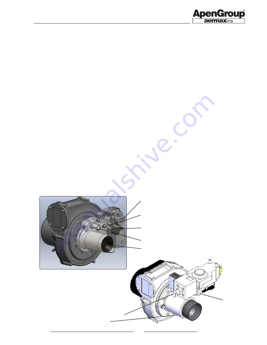
AKY
VENTURI
GAS INTAKE PRESSURE
CONNECTOR (IN)
OFFSET ADJUSTMENT
GAS PRESSURE CONNECTOR
ON BURNER (OUT)
PRESSURE CONNECTOR
FOR OFFSET ADJUSTMENT
CO
2
ADJUSTMENT
VENTURI
OFFSET AD-
JUSTMENT
CO
2
ADJUSTMENT
AKY100
AKY032, 034, 050, 070
6.3. First start-up
The boiler is supplied already set up and tested for the gas
specified on the nameplate. Before turning on the boiler, check
the following:
•
make sure the gas being supplied matches the gas for which
the boiler has been set up;
•
check, with the pressure intake "IN" on the gas valve, that
the valve input pressure corresponds to that required for
the type of gas being used;
•
check that the pressure inside the hydraulic circuit is between
1.2 and 1.6 bar;
•
check that electrical connections correspond to those
indicated in this manual or other wiring diagrams enclosed
with the machine;
• check that efficient earthing connections have been completed,
carried out as specified by current safety regulations;
To turn on the boiler, follow the instructions below:
•
provide voltage to the fan heater and, in case of fan heaters
equipped with a speed regulator, set the switch to winter
position and select maximum speed (5);
•
make sure that an ambient thermostat or SmartEASY/WEB
is connected to the boiler.
•
provide voltage to the boiler using the main switch after having
ensured that the three-pin plug is connected to the boiler;
•
when power voltage is provided to the boiler and ID2-IDC2
contact is closed on boiler PCB, the ignition cycle starts;
•
if APEN or Smart EASY/WEB remote control is connected,
refer to the relevant manual for the ignition cycle start
procedure, then continue with the following instruction.
Sometimes, when turned on for the first time, the burner cannot ignite
because there is air in the gas pipe. This will lock out the boiler. You
will need to reset the equipment and repeat the operation until it
ignites (for unlocking operations use the buttons on boiler display).
6.4. Analysis of combustion
Wait until the boiler reaches the maximum output.
Check again that the input pressure in the valve corresponds
to the value required; adjust if necessary.
Perform the combustion analysis to verify that the level of CO
2
corresponds the values contained in the table "GAS SETTINGS".
If the measured value is different, turn the adjustment screw
on the Venturi pipe. Loosening the screw will increase the CO
2
level, screwing it down will decrease the level.
Position the boiler at minimum capacity, check that CO
2
is equal
to or slightly lower than the value detected at maximum capacity
(up to -0.3%). If the values do not match, screw or loosen the
OFFSET screw respectively to increase or decrease the CO
2
level and repeat the procedure.
Flue cleaning function
The boiler can be forced to the maximum or minimum capacity
with the flue cleaning function. This function can be carried
out from the LCD display in REg menu with Hi (maximum heat
output) or Lo (minimum heat output) function.


