background image

23

code HC0100.00GB ed.A-1509

HY

AQUAPUMP HYBRID

  HYBRID HEATER

Pipe pressure drop

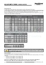
The table below contains pressure drop values of pipes for flow rate multiple values of fan heaters.

The drop is indicated in kPa per 1 metre of linear length; the calculation must be made by calculating the equivalent length of the 
pipe. The distance of the fan heater from the boiler must be duplicated. Drops are given for glycol-free 70-75°C water; for water 
glycol mix, multiply the drops by the given factor. The last line contains the volume in litres per 1 metre of pipe.

Pressure drops identified due to the various components inserted in the hydraulic system must be added up to the pipe length, 

according to the values indicated in the table below.

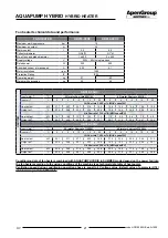
Glycol coefficients

The table just above contains the freezing temperatures of water and glycol mixes. 
Using a water and glycol mix, it is necessary to increase pressure drops of pipes and fan heaters according to the following 

coefficients:

• 

for a glycol mix equal to 

10%

 of volume multiply by 

1.07

• 

for a glycol mix equal to 

20%

 of volume multiply by 

1.15

• 

for a glycol mix equal to 

30%

 of volume multiply by 

1.22

All data refer to a FERNOX ALPHI11 monopropylene glycol and water mix recommended by APEN GROUP 

Other types of glycol, different from the recommended one, may invalidate the product warranty.

Pressure drops in kPa for 1 metre of linear length

Water flow rate

Steel pipes

Copper pipes

l/h

3/4"

1"

1"1/4

1"1/2

2"

20/22

25/28

32/35

39/42

51/54

                      600 

0.15

0.05

0.18

0.06

0.02

                      900 

0.31

0.10

0.03

0.35

0.12

0.04

                    1,200 

0.55

0.18

0.05

0.02

0.60

0.20

0.07

0.03

                    1,500 

0.82

0.26

0.07

0.03

0.30

0.10

0.04

                    1,800 

0.36

0.10

0.04

0.01

0.42

0.13

0.05

0.01

                    2,100 

0.49

0.13

0.06

0.02

0.52

0.17

0.07

0.02

                    2,400 

0.65

0.16

0.08

0.03

0.70

0.21

0.09

0.03

                    3,000 

0.24

0.11

0.04

0.27

0.12

0.04

                    3,600 

0.34

0.16

0.06

0.35

0.17

0.06

                    4,200 

0.45

0.21

0.07

0.53

0.22

0.07

                    4,800 

0.59

0.21

0.08

0.28

0.08

Water content l/m

0.37

0.59

1.20

1.39

2.22

0.31

0.49

0.80

1.19

2.04

Equivalent                        

length in m

Steel pipes

3/4"

1"

1"1/4

1"1/2

2"

 45° bend 

0.3

0.3

0.6

0.6

0.6

 90° bend 

0.6

0.6

0.9

1.2

1.5

 90° bend with wide radius  

0.6

0.6

0.6

0.6

0.9

 T-shaped fitting 

1.5

1.5

1.8

2.4

3.0

 check valve 

1.5

1.5

2.1

2.7

3.3

 gate valve 

0.3

0.3

0.3

0.3

0.3

Table of freezing temperatures

Glycol %

25

30

35

40

Freezing temperature

-11°C

-15°C

-18°C

-22°C

WARNING: check that the minimum water content of pipes for the system is 35 litre for model HY434 and 45 
litres for model HY534. If this is not the case, provide for pipes with greater diameter or equip the system 
with a reservoir having suitable volume.

Summary of Contents for Aermax Series

Page 1: ...ed A 1509 HY Use Installation and Maintenance Manual HYBRID HEATER AQUAPUMP HYBRID GB This manual cannot be copied in part or in full for disclosure to third parties without the prior written consent...

Page 2: ...2 code HC0100 00GB ed A 1509 HY AQUAPUMP HYBRID HYBRID HEATER...

Page 3: ...rettiva compatibilit elettromagnetica 2004 108 CE Electromagnetic Compatibility Directive 2004 108 EC Direttiva Bassa Tensione 2006 95 CE Low Voltage Directive 2006 95 EC Direttiva Erp 2009 125 CE Erp...

Page 4: ...4 code HC0100 00GB ed A 1509 HY AQUAPUMP HYBRID HYBRID HEATER...

Page 5: ...5 code HC0100 00GB ed A 1509 HY AQUAPUMP HYBRID HYBRID HEATER...

Page 6: ...6 code HC0100 00GB ed A 1509 HY AQUAPUMP HYBRID HYBRID HEATER...

Page 7: ...___________________________________________ _________________________________________________________________________________________ __________________________________________________________________...

Page 8: ...AMPUMP HYBRID size 26 3 5 Fan heater size 27 3 6 Operation 28 3 7 Temperature adjustment logic 29 4 USER S INSTRUCTIONS 30 4 1 Operation mode setting 30 4 2 Setting the time ranges 30 4 4 Operation mo...

Page 9: ...er maintenance 47 6 10 Boiler PCB parameters 48 6 11 Analysis of Lockouts BOILER FAULT 50 7 SERVICING INSTRUCTIONS HEAT PUMP 52 7 1 Start up 52 7 2 Control interface 52 7 3 Menu structure 53 7 4 Analo...

Page 10: ...ree no 37 of 22 01 2008 Law no 10 84 Standard UNI CIG 7129 Standard UNI CIG 7131 Law no 186 of 01 March 1986 Law no 10 91 Law no 192 05 of 19 08 2005 Legislative Decree no 311 of 29 12 2006 and subseq...

Page 11: ...t wear safety shoes with non slip sole in particular in environments with slippery floor Gloves Suitable protective gloves must be used during cleaning and maintenance operations Mask and goggles A re...

Page 12: ...e heater from the mains power supply using the switch located on the electrical system and or on the shut out devices If the equipment is faulty and or incorrectly operating switch it off and do not a...

Page 13: ...arameters AEL 8 h and 12 h TWA 1000 ml m3 for each of the two components Respiratory protection For rescue and maintenance work in storage tanks use self contained breathing apparatus Vapours are heav...

Page 14: ...llow taking full advantage of the renewable energy in terms of efficiency and costs The smart and combined use of the two systems allows the highest level of energy saving by the end user with the use...

Page 15: ...ed and provided with protection grille in compliance with standard EN 60335 household and similar electrical appliances safety Fans are installed on the unit through the interposition of rubber anti v...

Page 16: ...emperature sensors on boiler side water flow rate value reading through the remote flowmeter as well as all the other safety devices and any malfunction signals of the boiler itself Optional indoor un...

Page 17: ...45 C Protection Rating IPX5D IPX5D Hydraulic circuit Maximum circulator power kW 0 076 0 076 Expansion reservoir l 8 0 8 0 Maximum working pressure bar 3 0 3 0 Water content l 5 0 5 3 Minimum system w...

Page 18: ...rogen oxides NOx Hi 0 of 02 4 22ppm 39mg kWh Nitrogen oxides NOx Hs 0 of 02 4 20ppm 35mg kWh Fumes temperature C 75 48 Pressure available at the flue Pa 120 Electrical Characteristics Boiler supply vo...

Page 19: ...ssor Type Number Twin rotary DC inverter 1 Scroll DC inverter 1 Absorbed power in cooling mode 1 kW 2 73 3 42 Absorbed power in cooling mode 2 kW 2 59 3 32 Absorbed power in heating mode 3 kW 2 90 3 5...

Page 20: ...97 11 62 2 15 5 40 55 8 32 1 84 4 52 10 28 1 60 6 40 Performance referred to instantaneous power according to EN14511 without defrosting contribution Plate data of the heat pump in COOLING mode HY434...

Page 21: ...2 22 5 25 8 29 0 Air flow rate 1 125 m h MIN speed 3V Heat output kW 16 1 14 9 13 7 12 5 11 3 11 0 9 8 8 6 7 4 6 2 Output air T C 42 7 44 6 46 4 48 3 50 1 29 1 31 0 32 8 34 7 36 5 AB034 00H0 Input wat...

Page 22: ...r only through HP in operation periods in which the boiler is bypassed Fan heater pressure drop Drops are estimated with glycol free 65 C water increase the drop depending on the glycol percentage acc...

Page 23: ...lene glycol and water mix recommended by APEN GROUP Other types of glycol different from the recommended one may invalidate the product warranty Pressure drops in kPa for 1 metre of linear length Wate...

Page 24: ...HP input HP output EV1 GAS solenoid valve EV2 Secondary solenoid valve FLUX Flowmeter NTC NTC probes PI Circulator VLV3V 3 way valve SRA Plate rapid exchanger STF Fumes temperature probe VF Burner fa...

Page 25: ...stalled so as to allow maintenance and repair operations The warranty does not cover the costs for platforms or handling equipment required for any operations All maintenance and check operations must...

Page 26: ...utions DISEGNO DESCRIZIONE 1 12 Quote senza indicazione di tolleranza Classe di Tolleranza ISO 2768 M DISEGNO DI PROPRIETA APEN GROUP spa E VIETATA LA RIPRODUZIONE E LA DIFFUSIONE ANCHE PARZIALE SENZA...

Page 27: ...09 HY AQUAPUMP HYBRID HYBRID HEATER 3 5 Fan heater size HC0047 C2 003 765 730 80 345 165 430 595 425 40 380 G3 4 547 30 72 72 60 AB018IT 00H0 555 1390 165 430 595 645 705 40 555 90 60 108 45 G1 30 30...

Page 28: ...ter DHW temperature control as shown in the table below System type Temperature Reference Domestic Hot Water 0 Fan heater No Air 1 Tank No Water 2 Tank DHW Water Present 3 Fan heater DHW Air Present P...

Page 29: ...ial for ST Xd2 Differential for winter operation only to distinguish the limit T below which the boiler must be activated as well WINTER SETUP The equipment operation during the heating phase requires...

Page 30: ...selected For TEMPORARY OFF duration the following icon is displayed on the main screen 4 2 Setting the time ranges To programme the time ranges it is necessary to press the MENU icon in the main scre...

Page 31: ...ch it is possible to check the several active setpoints for the type of configured system HYBRIDO PARAMETERS and to monitor the operation parameters of the machine in real time HYBRIDO MONITORING thro...

Page 32: ...on the working procedures and safety regulations Recoveredpackagingmaterialsmustbeseparatedanddisposed of according to applicable regulations in the country of use While unpacking the unit check that...

Page 33: ...h maximum screw diameter of M10 Note Make sure that the type of dowel not supplied with the equipment is suitable for the type of wall and sufficient to support the weight of the fan heater 3 Fix the...

Page 34: ...nected Connections to the terminal box must be carried out by qualified personnel only The connection terminal box is located under the panel on which the main switch with door lock is fixed The termi...

Page 35: ...fit upstream of the fan heater amultipoleisolatorfittedwithasuitable electric protection element Carry out the connections according to the diagram below Control connections 1 GND BLUE 2 TACH GREEN 3...

Page 36: ...k a hydraulic separator or a reservoir and at the same time to control a domestic water boiler with a second setpoint for domestic hot water supply In this case the reference temperature TREF controll...

Page 37: ...is activated Domestic Set STDOM Domestic hot water temperature setpoint displayed for operation modes 2 and 3 only Domestic Xd Differential value that distinguishes the domestic request activation or...

Page 38: ...lling or water replenishment operations are the same for all models FILLING Make sure that connections between indoor unit system andAQUAPUMP HYBRID have been carried out correctly respecting delivery...

Page 39: ...int Gas filter without stabiliser N B Avoid using threaded connections directly on the gas connection of the equipment Hydraulic connections According to the instructions of par 5 4 prepare the hydrau...

Page 40: ...lled therefore it is provided with a pipe 19 for condensation drain The machine is equipped with a sealed fume trap with internal float that prevents fume outflow from condensate drain also if water i...

Page 41: ...____________________________________________ _________________________________________________________________________________________ _________________________________________________________________...

Page 42: ...at the equipment has been tested and set up for LPG G31 HY434NL xxx2 2 indicates that the equipment has been tested and set up for L natural gas G25 HY434HU xxx3 3 indicates that the equipment has bee...

Page 43: ...S CONSUMPTION 15 C 1013mbar m3 h 3 71 0 80 TYPE OF GAS G25 cat L LL TYPE of MACHINE HY434 534 CATEGORY According to the country of destination see previous table SUPPLY PRESSURE mbar 25 min 20 max 30...

Page 44: ...instruction Sometimes when turned on for the first time the burner cannot ignite because there is air in the gas pipe This will lock out the boiler You will need to reset the equipment and repeat the...

Page 45: ...rrespondstothevaluerequired for the type of gas that you are using 2 the combustion analysis procedure is performed as described in paragraph 6 4 3 the CO2 level is within the values indicated for the...

Page 46: ...R99 C31 C2 SW1 R94 C52 R34 F8 C56 R89 C14 R25 R106 R77 C27 R49 R10 R58 C40 C20 C8 Q5 R45 R62 RL2 C22 R64 D3 C23 R32 U11 LC6 C11 R70 R40 D9 D1 R35 R110 R42 R31 R59 R96 TS1 R38 D5 D20 Q3 R23 D2 R55 R26...

Page 47: ...the PCB signals the fault F99 configuration error 6 9 Exchanger maintenance Precautions for use The boiler heat exchanger must be used in the following conditions The fuel used must have a sulphur con...

Page 48: ...nition 0 255 b9 sec 15 Combustion chamber post cleaning time FAN ON 0 255 b10 5 Motor rpm increase for each b11 seconds 1 100 b11 sec 2 Time interval for motor rpm increase 1 100 b12 30 Antifreeze mod...

Page 49: ...Fumes temperature operation 0 modulation only 1 burner OFF TH3 C 103 Temperature upper limit autoreset if NTC3 TH3 0 140 Hydraulic circuit WATER PRESSURE control S5 3 Pressure probe B2 output enablin...

Page 50: ...equipment and CPU for more than 60 seconds ACF equipment or CPU SMART PCB broken Auto reset F15 the CPU SMART PCB sent the ignition signaltotheequipmentwhich after300 seconds has not lit the flame yet...

Page 51: ...ipment F82 Preventive alarm water pressure PRH TH5 Excessive pressure inside water circuit check the hydraulic circuit load or the expansion reservoir F85 Nowatercirculation FLHvalueisequal to zero Wa...

Page 52: ...to enter parameter setting menu and to set the value of summer winter and domestic water setpoint UP key In parameter setting mode it allows to go to an upper menu or to increase a parameter value wh...

Page 53: ...nu see par 4 4 7 5 Display Standard viewing displays water outlet temperature from plate exchangeroftheheatpump thereforebeforebeingpost heated bytheboilerifthelatterisoperating intenthsofadegreeCelsi...

Page 54: ...E06 Flow switch E18 High temperature E61 Input water probe E62 Output water probe E63 Compressor intake probe E64 Compressor delivery probe HP pressure switch E65 High pressure transducer E66 Low pres...

Page 55: ...to OFF Close water taps Switch the main earth leakage switch to OFF If the temperature drops below 0 C there is a real risk of frost provide for a water glycol mix in the system otherwise empty the h...

Page 56: ...check the correct operation of the unit OPERATION 1 month 4 months 6 months Water circuit filling x Presence of bubbles in water circuit x Check the correct operation of control and safety devices x C...

Page 57: ...space heating energy efficiency of the package offered figure 1 AQUAPUMP HY434 MODEL Seasonal space heating energy efficiency of the boiler I 92 6 1 Temperature check 1 1 0 2 Additional boiler 2 I x 0...

Page 58: ...of the package of products provided for in this fiche may not correspond to its actual energy efficiency once installed in a building as the efficiency is influenced by further factors such as the hea...

Page 59: ...I 0 66 0 78 0 72 0 83 III 0 76 IV 0 30 package without hot water reservoir package with hot water reservoir Table 5 Annex IV or EU Regulation no 811 2013 For the purposes of figure 1 weighing of boile...

Page 60: ...60 code HC0100 00GB ed A 1509 HY AQUAPUMP HYBRID HYBRID HEATER...

Reviews: