background image

10

11

Mode/Channel

Value

Function

Type of 

control

1

2

3

17

0-7

8-15

16-23

24-31

32-39

40-47

48-55

56-63

64-71

72-79

80-87

88-95

96-103

104-111

112-119

120-127

128-135

136-143

144-151

152-159

160-167

168-175

176-183

184-191

192-199

200-207

208-215

216-223

224-231

232-239

240-247

248-255

MACRO SELECTION

No function

Macro 1

Macro 2

Macro 3

Macro 4

Macro 5

Macro 6

Macro 7

Macro 8

Macro 9

Macro 10

Macro 11

Macro 12

Macro 13

Macro 14

Macro 15

Macro 16

Macro 17

Macro 18

Macro 19

Macro 20

Macro 21

Macro 22

Macro 23

Macro 24

Macro 25

Macro 26

Macro 27

Macro 28

Macro 29

Macro 30

Macro 31

step

step

step

step

step

step

step

step

step

step

step

step

step

step

step

step

step

step

step

step

step

step

step

step

step

step

step

step

step

step

step

step

18

0-31

32-63

64-95

96-127

128-143

144-159

160-191

192-223

224-255

SHUTTER/STROBE

Shutter closed

Shutter open

Strobe-effect from slow to fast

Shutter open

Opening pulses in sequences from slow to fast

Closing pulses in sequences from fast to slow

Shutter open

Random strobe-effects from slow to fast

Shutter open

step

step

proportional

step

proportional

proportional

step

proportional

step

19

4

0-255

DIMMER

Dimmer intensity from 0% to 100%

proportional

8. Control board

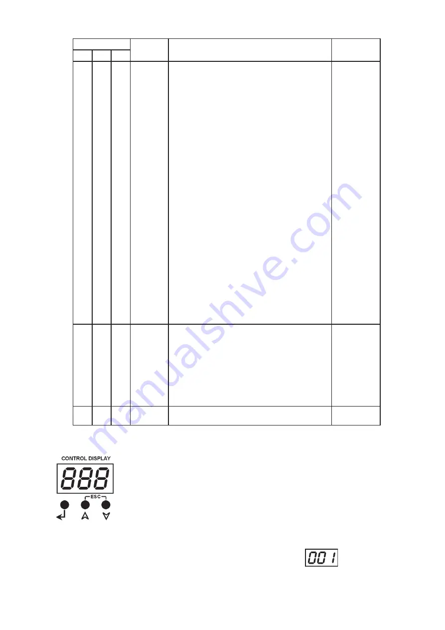
The control panel situated on the top cover of the ArcPower 144 allows DMX address-

ing, calling Built-in programs and setting the fixture behaviour.

Control elements:

[ENTER]

 button- enters menu, confirms adjusted values and leaves menu. 

[UP]

 button and 

[DOWN]

 button- moves between menu items on the the same level, 

sets values.

In order to leave the menu without saving value, press [UP] and [DOWN] at the same 

time.

After switching on the ArcPower 144, the display shows the initial DMX address: 

Summary of Contents for ArcPower 144

Page 1: ...USER MANUAL ArcPower 144 Version 2 0...

Page 2: ......

Page 3: ...rating 6 5 2 Master slave operating 8 6 Control menu map 9 7 DMX protocol 10 8 Control board 11 8 1 Addressing the ArcPower 144 12 8 2 Program running 12 8 3 Manual mode 13 8 4 Test sequences 13 8 5 S...

Page 4: ...ried out by a qualified employee Do not connect this unit to a dimmer pack Use a source of AC power that complies with local building and electrical rules AC power has to have both overload and short...

Page 5: ...plug A 3 prong grounding type plug must be installed following the manufacturer s instructions The earth has to be connected Cord plug connections Cable Pin International Brown Live L Light blue Neutr...

Page 6: ...roller If your DMX controller has RJ45 socket for DMX output use RJ45 patch cable for connection with the ArcPower 144 RJ45 plug DMX 512 XLR plug male View facing pins Front view of the plug Pin 1 Not...

Page 7: ...nd all its connected LED modules is 80 metres Single ArcPower 144 installation Multiple ArcPower 144 installation Connect the DMX output of the first ArcPower 144 with the DMX input of the next ArcPow...

Page 8: ...ource 7 RGBW each other because white LEDs will not light 5 2 Master slave operating 1 Unplug from the mains before installation 2 Connect the LED module to the fixtures 3 Connect the DMX output of th...

Page 9: ...OFF On Edl E P 1 E P 2 E P 3 S 01 S 30 End rE1 0 255 diM 0 255 FA t 0 255 S tl 0 255 COP MAn rE1 0 255 Gr1 0 255 bL1 0 255 0 255 MAC 0 255 Str 0 255 diM 0 255 tSt St A MSt E P 1 P06 SLA SPE VEr bAL On...

Page 10: ...3 0 255 Blue LED 2 Blue LED saturation control 0 100 proportional 8 0 255 White LED 2 White LED saturation control 0 100 proportional ZONE 3 9 7 1 0 255 Red LED 3 Red LED saturation control 0 100 pro...

Page 11: ...8 0 31 32 63 64 95 96 127 128 143 144 159 160 191 192 223 224 255 SHUTTER STROBE Shutter closed Shutter open Strobe effect from slow to fast Shutter open Opening pulses in sequences from slow to fast...

Page 12: ...the current step and a Standing time the time during which effects last in the current step Programming procedure 1 Enter Edl menu 2 Press UP or DOWN to select the desired program which you wish to ed...

Page 13: ...red LED 3 saturation value 0 255 rE4 a red LED 4 saturation value 0 255 Gr3 a green LED 3 saturation value 0 255 Gr4 a green LED 4 saturation value 0 255 bL3 a blue LED 3 saturation value 0 255 bL4 a...

Page 14: ...esired number of the zone from 0 to 6 The number of the zone distinguishes individual zones of the ArcPower 144 which is controled via RS 232 interface Use UP and DOWN buttons to select desired zone a...

Page 15: ...ff and on the fixture to leave this option 3 It is recommended that you exit all programs before running the Software Uploader 4 Start the Software Uploader program Select desired COM and then click C...

Page 16: ...lect SPE in main menu of the ArPower 144 press ENTER use UP and DOWN buttons to select Zon The option enables to select desired number of the zone from 0 to 6 Press ENTER use UP and DOWN buttons to se...

Page 17: ...means DMX value of the green colour 0 255 b means DMX value of the blue colour 0 255 means end of character sequence values of colours have to be separated by a comma Examples zone 0 234 126 165 zone...

Page 18: ...colour Max load per zone 36 LED s in RGB mode 42 LED s in RGBW mode Total load 144 LED s in RGB mode 168 LED s in RGBW mode Maximum total cable length between one LED zone output and all its connecte...

Page 19: ...e 1 Before replacing the fuse unplug mains lead 2 Unscrew the fuse holder on the rear side of the ArcPower 144 with a fitting screwdriver from the housing anti clockwise 3 Remove the old fuse from the...

Page 20: ...20...

Reviews: