


UG-1882
Rev. 0 | Page 6 of 28
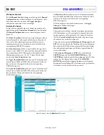
Table 3. Resistor Dividers for Setting A0 through A7 DC
Input Voltages
Channel Default Voltage
Series
Resistor
Shunt
Resistor
IN0
CH0
1
R2
R9
IN1
CH1
1
R4
R10
IN2
2.5 V
R6
R11
IN3
2.5 V
R8
R12
IN4
2.5 V
R5
R19
IN5
2.5 V
R7
R20
IN6
2.5 V
R15
R23
IN7
2.5 V
R16
R24
IN8
2.5 V
R137
R144
IN9
2.5 V
R139
R145
IN10
2.5 V
R75
R77
IN11
2.5 V
R76
R78
IN12
2.5 V
R85
R90
IN13
2.5 V
R86
R91
IN14
2.5 V
R88
R92
IN15
2.5 V
R89
R93
1
CH0 and CH1 are voltages that are supplied externally through J1 or J3, and
J2 or J4.
Hardware Configurations for Supporting AD4696
Polarity Modes
As described in the
data sheet, the AD4696 analog
inputs (IN0 through IN15) include channel pairing and polarity
mode features to support both single-ended and pseudo differential
input types. Each of these options can be evaluated by making
simple hardware modifications and associated configuration
changes to the register settings of the AD4696 within the AD4696
evaluation software (see the Memory Map View section for
instructions on how to modify the contents of the registers of
the AD4696).
To ensure correct operation of the AD4696, the EVAL-
AD4696FMCZ hardware must be configured with the correct
voltages on each analog input, dictated by the operating input
voltage specification in the AD4696 data sheet. To ensure
correct operation of the AD4696, the EVAL-AD4696FMCZ
hardware must be configured with the correct voltages on each
of the following analog inputs:
•
When COM pairing is selected
•
Unipolar mode enabled = COM must be driven to 0 V
•
Pseudo bipolar mode enabled = COM must be driven
to V
REF
/2 V
•
When even or odd numbered input pairing is selected
•
Unipolar mode enabled = odd numbered must be
driven to 0 V
•
Pseudo bipolar mode enabled = odd numbered input
must be driven to V
REF
/2 V
The device does not function as described in the AD4696 data
sheet if the hardware configuration does not match the software
settings as described in the previous list.
The COM voltage can be tied to ground or V
REF
/2 using the JP6
solder link (see Figure 24 and Table 4). Amplifier A8 produces a
dedicated V
REF
/2 V dc voltage utilizing a matched resistor
network from the selected VREF source. JP6 selects whether the
COM pin is connected directly to the EVAL-AD4696FMCZ
ground (for example, 0 V) or the V
REF
/2 V output of A8. Ensure
that JP6 is configured appropriately for the channel configuration
settings selected via the AD4696 evaluation software. By
default, the COM pin is connected to AGND through JP6.
When pairing even and odd numbered inputs, modify the
resistor divider components on the input of the ADC driver
connected to the relevant odd numbered channel to achieve the
required voltage (see the Configuring DC Channels (IN2
Through IN15) section). By default, the odd numbered inputs
from IN3 through IN15 are driven to V
REF
/2 V via the resistor
dividers listed in Table 3. To drive any given odd numbered
input to 0 V instead, it is recommended to populate the
corresponding shunt resistor with a 0 Ω resistor and to not
populate the corresponding series resistor.
Table 4. JP6 Settings and COM Voltage
JP6 Setting
COM Voltage
A
V
REF
/2 V
B (Default)
0 V
Recommended ADC Drivers
As described in the Evaluating AD4696 AC Performance (IN0
and IN1) section and the Configuring DC Channels (IN2
Through IN15) section, the EVAL-AD4696FMCZ is populated
by default with an
(A0) functioning as the ADC
driver for the IN0 and IN1 AD4696 inputs and seven
devices functioning as the ADC drivers for the remaining 14
AD4696 inputs (IN2 to IN15). These ADC drivers (A0 to A7)
can be replaced with other amplifiers, provided they are
available in a pin-compatible dual-amplifier, 8-lead MSOP
package. Several recommendations include the following:
•
•
•
The AD4696 is compatible with a wider variety of ADC drivers
than many multichannel SAR ADCs. Traditionally, SAR ADCs
require ADC drivers with high bandwidth to settle voltage steps
that occur at its inputs during the conversion process. The
inputs of the AD4696 are designed to reduce these voltage steps,
which reduces the drive requirements of the amplifiers acting as
the ADC drivers. See the AD4696 data sheet for more information.
When using the ADA4610-2 and the ADA4077-2 or using
larger resistors between the amplifier and AD4696 input, it is
recommended to enable the analog input high-Z mode on the
corresponding channels setting the AINHIZ_EN bit in the
relevant per channel configuration registers (CONFIG_IN0
through CONFIG_IN15). See the Memory Map View section
for instructions on how to configure these register settings.


