


UG-1882
Rev. 0 | Page 5 of 28
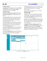
(see Figure 26). This flexibility allows prototyping of many
potential driver configurations. Both A0 amplifiers are
configured as unity-gain buffers by default.
The CH0 and CH1 signals from the SMA connectors can be
routed to either the non inverting or inverting inputs of the A0
amplifiers to support non inverting and inverting amplifier
configurations. Table 1 lists the hardware modifications required
to route the CH0 and CH1 signals appropriately for unity gain,
non inverting gain, and inverting amplifier configurations for
both IN0 and IN1 channels. DNI means do not insert.
Table 1. Hardware Settings for Routing to A0 Inputs
Configuration
IN0
IN1
Unity Gain Buffer
R1 = 0 Ω (default)
R3 = 0 Ω (default)
R13 = DNI (default)
R14 = DNI (default)
Non Inverting with
Gain
R1 = 0 Ω (default)
R3 = 0 Ω (default)
JP0 = Position B
JP1 = Position B
Inverting
R1 = DNI
R3 = DNI
JP0 = Position A
(default)
JP1 = Position A
(default)
Resistor dividers are provided on the non inverting inputs of the
CH0 and CH1 channels of A0 to provide a dc bias generated on
board via CHDR1 (see R2, R9, R4, and R10 in Figure 26). These
resistor dividers are not populated by default. Populate these
resistor dividers to drive the non inverting pins of A0 to a constant
dc voltage. When populating these resistor dividers while routing
an external signal to the non inverting inputs of A0, take care to
select the resistor sizes appropriately to achieve the desired
attenuation of the dc and ac voltage components.
When modifying the A0 amplifier (currently populated with
) configurations to non default settings, it is
recommended to consult the ADA4805-2 data sheet for the
selected amplifiers, and consider amplifier stability, noise,
distortion, power consumption, and output current when
selecting amplifiers and passive component values. When
evaluating ac performance, it is also recommended to use
NP0 or C0G capacitors in the signal path to avoid distortion
degradation associated with the voltage coefficient specifications
of other capacitor material types (this applies to all capacitors
surrounding the A0 amplifiers in Figure 26).
Configuring DC Channels (IN2 Through IN15)
The analog inputs of the
are unipolar and accept inputs
in the range from 0 V to V
REF
. For this reason, additional
amplifiers are provided on the EVAL-AD4696FMCZ hardware,
which generate low noise dc voltages from the reference source
that can be used to drive the IN2 through IN15 channels on the
AD4696 to fixed dc voltages. Channel IN2 through Channel IN15
are therefore considered dc channels and are provided to
evaluate noise performance and settling accuracy performance
when sequencing the multiplexer between channels or channel
configurations.
There are two dc signals labeled CHDR1 and CHDR2 in
Figure 26, Figure 27, and Figure 28. CHDR1 and CHDR2 are
generated by two
devices configured as unity-gain
buffers (U7 and U9 in Figure 28). The inputs of U7 and U9 are
connected to the output of the voltage reference (U3) by default.
Therefore, CHDR1 and CHDR2 are equal to VREF by default.
CHDR1 (the output of U7) is routed to the amplifiers in A1
through A3, and CHDR2 (the output of U9) is routed to the
amplifiers in A4 through A7 to drive the IN8 through IN15
channels on the AD4696.
Component A1 through Component A7 are dual precision
amplifiers that function as the ADC drivers for the AD4696 IN2
through IN15 inputs (see Figure 26 and Figure 27). By default,
A1 through A7 are populated with the
and are fixed as
unity-gain buffers. LT6237 is a low noise amplifier suitable for
driving SAR ADCs in applications that involve switching.
The dc voltages for IN2 through IN15 channels can be modified
via resistor dividers at the inputs of U7 and U9 (see Table 2 and
Figure 28) or via resistor dividers at the inputs of A1 through A7
(see Table 3, Figure 26, and Figure 27). Modifying the resistor
dividers in Table 2 changes the voltages of CHDR1 and CHDR2,
and therefore changes the dc voltages on all downstream ADC
driver channels. To configure the voltages for each channel
independently from each other, it is recommended to use the
default configuration for the resistor dividers in Table 2 and
only modify the resistor dividers in Table 3.
When making any modifications to the resistor dividers in front
of the ADC drivers, A0 to A7, ensure that the total current load
demands for U7 and U9 do not violate the output current limit
specification of the ADA4841-1. The output current source
limitations of the ADA4841-1 is 30 mA (see the ADA4841-1
data sheet for more information). Ensure the total load of each
resistor divider is at least 10 kΩ. By default, each resistor divider
on each channel is populated with two 10 kΩ resistors. Thus, the
resistor dividers of each channel is equivalent to a 20 kΩ load,
and draws 0.5 mA each (when CHDR1 and CHDR2 are the default
5 V). To limit resistor thermal noise coupling into the AD4696
input channels, 0.1 µF capacitors are populated on the non
inverting inputs of A1 through A7 (see Figure 26 and Figure 27).
As described in the Evaluating AD4696 AC Performance (IN0
and IN1) section, CHDR1 is also routed to the amplifiers in A0
to supply a dc bias to the IN0 and IN1 ADC drivers. CHDR1 is
not connected to the inputs of A0 by default.
Table 2. Resistor Dividers for Setting CHDR1 and CHDR2
Signal
Reference Designators
Default Values
CHDR1
R53
0 Ω
R54
Do not insert
CHDR2
R58
0 Ω
R60
Do not insert


