background image

MAX MMS Servers - Photos and Specifications

15

MAX Servers: HT Home Theater and MMS Multimedia Servers

MMS-12S Multimedia Server  

Product Specifications 

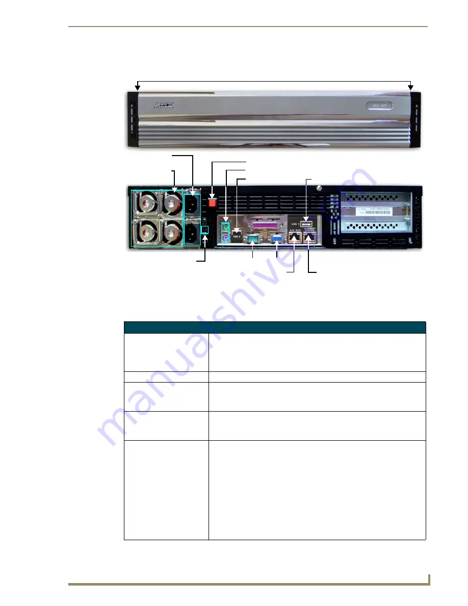
FIG. 8  

MMS-12S Multimedia Server

MMS-12S (FG 2178-08) Product Specifications

Storage capacity:

• 3 terabytes of storage space
• 300 DVD (7,500 CD) capacity (approximate values)
• Approximately 25 CDs can be stored in place of 1 DVD
• Uses a RAID 5 disc drive system

Power:

110-240 VAC, 50/60Hz

AC Current Draw (AMP): 

For each of the 2 power supplies:
• 3.40A - Bootup/Power Cycle Peak
• 2.06A - Normal Usage Peak

Front Panel Components:
(remove Faceplate to access)

• 12 hot-swappable 250GB hard drives
• Drive Status LEDs
• Ventilated front cover

Rear Panel Components:

• Two Removable Power Supplies
• Two Power Cable connectors: IEC connectors for AC power cables 

(included)

• Power On/Off button: Turns the MMS on/off
• Power Supply Reset button
• PS/2 Keyboard and Mouse ports
• USB ports 1 & 2: Type A USB connectors connect to MAX-AOM module(s) 

for audio distribution

• RS-232 port: DB-9 serial port for external control
• Parallel port: 

not used

• VGA port: DB15HD port provides VGA output

2 Removable

Power Supply Reset

2 Power cable

connectors

PS/2 keyboard & mouse ports

RS-232

VGA

USB 2

 port

A/V OUT

USB 1

 port

Power On/Off 

ETHERNET CONTROL


switched GB

 Control

 segment

(to NetLinx Master or PC)

power supplies

switched GB 

Content 

segment

(to MAX-AVM Modules)

(front)

Faceplate snaps on/off to allow access to the hard drives

(rear)

Summary of Contents for MAX Servers

Page 1: ...Operation Reference Guide MAX by AMX MAX Servers HT Home Theater and MMS Multimedia Servers Last Revised 9 10 2007 ...

Page 2: ...or after the RMA is cancelled will be refused AMX is not responsible for products returned without a valid RMA number AMX is not liable for any damages caused by its products or for the failure of its products to perform This includes any lost profits lost savings incidental damages or consequential damages AMX is not liable for any claim made by a third party or by an AMX Dealer for a third party...

Page 3: ...s 15 MMS 900 Multimedia Server 17 Product Specifications 18 MAX Servers Setup and Configuration 19 Overview 19 Networking Specifications for MAX Servers 19 Online Database 20 Mandatory 24 Hour Initialization Period HT Servers only 20 If Power Is Removed From the HT Server 20 Step 1 Connect a Mouse Keyboard and VGA Monitor 20 Step 2 Connect the Power Cable s and Apply Power 21 MMS 01S 02S 02SB and ...

Page 4: ...w 27 Accessing the Admin Menu via WinMAX 27 Accessing the Admin Menu via Direct Connection to the MAX Server 28 MAX Admin Menu Options Overview 28 System Information 29 IP Settings 30 Preparing the MAX Server for Receiving Periodic Updates 31 Output Module Setup 31 Adding New Modules to the System 32 Viewing all Modules in the System 33 Removing Modules From the System 33 RAID 5 Status 33 RAID 5 C...

Page 5: ...es Supported Formats 49 DVD Drives Compatible Formats 49 MAX Servers DVD Drives Used 49 MDL Series DVD Drives 50 Replacing HDDs in MAX Servers 51 Overview 51 Replacing HDDs in MMS Servers 51 Step 1 Identify the Drive That Needs To Be Replaced 51 Step 2 Physical Removal and Replacement of the Drives 54 Step 3 Rebuild the RAID Array 54 Step 4 Authenticate the New HDD 55 a Open a telnet session with ...

Page 6: ...ket Assemblies In the Rack 64 Step 5 Load the MMS Server Into the Rack 64 Rack Mounting HT and MMS 900 Servers 65 CAUTION Safety Instructions 66 Step 1 Install Chassis Sections Onto The Server Chassis 66 Step 2 Slide Intermediate Sections Into the Stationary Sections 67 Step 3 Attach the Extension Brackets 68 Step 4 Mount the Adapter Bars to the Rack Rail assemblies 68 Step 5 Mount the Rail Bracke...

Page 7: ...arch and select chapters titles and tracks Video is stored in native DVD format to fully capture the quality of the original video Music is stored in native audio CD format Additionally MAX servers provide playback of MP3 files MAX servers support up to 25 MAX AVM audio video modules via Ethernet MAX servers support 1 or 2 MAX AOM audio only modules each of which can distribute four zones of audio...

Page 8: ...as well as manage content from any Windows PC Refer to the WinMAX Software Instruction Manual available online at www amx com for information and instructions Related Documents The following AMX documents provide additional information on the HT Servers and related devices and are available online at www amx com Use the WinMAX software to add remove DVD CD content on the server and control playbac...

Page 9: ...t A V OUT USB 2 port Master ETHERNET CONTROL switched GB Control segment to NetLinx Master or PC switched GB Content segment to MAX AVMs and or MAX AVPs mouse ports Power switch cable connector Power ON OFF toggle switch IMPORTANT MAX HT Servers require a 24 hour initialization period This simply entails powering up the server and letting it charge and initiate for 24 hours before use Failure to a...

Page 10: ...atts Normal Usage Peak 1 5A 240V 360 watts Front Panel Components remove Faceplate to access MAX HT04 4 hot swappable 400GB hard drives MAX HT12 12 hot swappable 400GB hard drives DVD CDRW drive Drive Status LEDs Ventilated front cover Rear Panel Components Power Cable connector IEC connector for AC power cable included Master Power Supply switch Turns the power supply on off Power On Off toggle s...

Page 11: ...arance 3 front and 3 rear Included Accessories One 6 1 83m power cable One DVD one CD Rack Mounting Kit Installation Guide Other AMX MAX Equipment MAX AVP Audio Video Player FG 2178 51 MAX AVM Audio Video Module FG 2178 50 MAX AOM Audio Only USB Module FG 2178 55 MAX AOM EX Expansion Kit FG 2178 56 MAX MDL200 Multi Disc Loader FG 2179 01 Certifications UL Listed E252362 FCC CE Required Firmware ve...

Page 12: ...MAX HT Servers Photos and Specifications 6 MAX Servers HT Home Theater and MMS Multimedia Servers ...

Page 13: ...e power supply on off Power On Off button Turns the MMS on off PS 2 Keyboard and Mouse ports USB port Type A USB connector connects to one MAX AOM module for additional audio distribution RS 232 port DB 9 serial port for external control Parallel port not used VGA port DB15HD port provides VGA output ETHERNET CONTROL port RJ 45 Gigabit Ethernet port provides 1000 100 10 Mb s network connectivity b...

Page 14: ...A weighted Frequency Response 20Hz to 20kHz Dynamic Range 110dB Dimensions HWD without rack ears 1 75 x 17 3 x 20 4 45 cm x 43 94 cm x 50 80 cm 1 RU mounts in a standard 19 equipment rack Weight 26 40 lbs 11 97 kg Operating Environment Operating Temperature 10º to 35º C Operating Relative Humidity 20 to 80 non condensing Minimum Ventilation Clearance 3 front and 3 rear Operating acoustic noise 62 ...

Page 15: ...e MMS on off PS 2 Keyboard and Mouse ports USB port Type A USB connector connects to one MAX AOM module for additional audio distribution RS 232 port DB 9 serial port for external control Parallel port not used VGA port DB15HD port provides VGA output ETHERNET CONTROL port RJ 45 Gigabit Ethernet port provides 1000 100 10 Mb s network connectivity between the MMS and the NetLinx Master or PC A V OU...

Page 16: ...10dB Dimensions HWD without rack ears 1 75 x 17 3 x 20 4 45 cm x 43 94 cm x 50 80 cm 1 RU mounts in a standard 19 equipment rack Weight 28 lbs 12 70 kg Operating Environment Operating Temperature 10º to 35º C Operating Relative Humidity 20 to 80 non condensing Minimum Ventilation Clearance 3 front and 3 rear Operating acoustic noise 62 dBA Included Accessories One 6 1 83m power cable One DVD one C...

Page 17: ...USB port Type A USB connector connects to one MAX AOM module for additional audio distribution RS 232 port DB 9 serial port for external control Parallel port not used Power Cable connector IEC connector for AC power cable included VGA port DB15HD port provides VGA output ETHERNET CONTROL port RJ 45 Gigabit Ethernet port provides 1000 100 10 Mb s network connectivity between the MMS and the NetLin...

Page 18: ...10dB Dimensions HWD without rack ears 1 75 x 17 3 x 20 4 45 cm x 43 94 cm x 50 80 cm 1 RU mounts in a standard 19 equipment rack Weight 28 lbs 12 70 kg Operating Environment Operating Temperature 10º to 35º C Operating Relative Humidity 20 to 80 non condensing Minimum Ventilation Clearance 3 front and 3 rear Operating acoustic noise 62 dBA Included Accessories One 6 1 83m power cable One DVD one C...

Page 19: ...PS 2 Keyboard and Mouse ports USB ports 1 2 Type A USB connectors connect to MAX AOM module s for audio distribution RS 232 port DB 9 serial port for external control Parallel port not used VGA port DB15HD port provides VGA output ETHERNET CONTROL port RJ 45 Gigabit Ethernet port provides 1000 100 10 Mb s network connectivity between the MMS and the NetLinx Master or PC A V OUT port RJ 45 Gigabit ...

Page 20: ...80 non condensing Minimum Ventilation Clearance 3 front and 3 rear Operating acoustic noise 62 dBA Included Accessories One 6 1 83m power cable One DVD one CD Rack mounting kit Other AMX MAX Products MAX AVM Audio Video Module FG 2178 50 MAX AOM Audio Only USB Module FG 2178 55 MAX AOM EX Expansion Kit FG 2178 56 MAX MDL200 Multi Disc Loader FG 2179 01 MMS HDD250G Replacement 250MB HDD FG 2178 250...

Page 21: ...ard drives Drive Status LEDs Ventilated front cover Rear Panel Components Two Removable Power Supplies Two Power Cable connectors IEC connectors for AC power cables included Power On Off button Turns the MMS on off Power Supply Reset button PS 2 Keyboard and Mouse ports USB ports 1 2 Type A USB connectors connect to MAX AOM module s for audio distribution RS 232 port DB 9 serial port for external ...

Page 22: ...s HWD without rack ears 3 50 x 17 3 x 20 8 89 cm x 43 94 cm x 50 80 cm 2 RU mounts in a standard 19 equipment rack Weight 64 10 lbs 29 7 kg Operating Environment Operating Temperature 10º to 35º C Operating Relative Humidity 20 to 80 non condensing Minimum Ventilation Clearance 3 front and 3 rear Operating acoustic noise 62 dBA Included Accessories Two 6 1 83m power cables One DVD one CD Rack moun...

Page 23: ...er DVD CDRW tray Power LED green Bootup Disc LED yellow Fan LED red Power button Storage Disc Drives Hard drive front Reset button activity LEDs 4 Power cable connectors PS 2 keyboard VGA RS 232 USB 2 port A V OUT USB 1 port ETHERNET CONTROL switched GB Control segment to NetLinx Master or PC switched GB Content segment to MAX AVM Modules mouse ports rear ...

Page 24: ...yboard and Mouse ports USB ports 1 2 Type A USB connectors connect to MAX AOM module s for audio distribution RS 232 port DB 9 serial port for external control VGA port DB15HD port provides VGA output Parallel port not used ETHERNET CONTROL port RJ 45 Gigabit Ethernet port provides 1000 100 10 Mb s network connectivity between the MMS and the NetLinx Master or PC A V OUT port RJ 45 Gigabit Etherne...

Page 25: ...he same as AVMs each HT server supports up to a total of 25 AVPs AVMs These steps apply to all MAX servers unless otherwise noted Networking Specifications for MAX Servers It is required that the control segment of the network using the ETHERNET CONTROL connector is kept separated from the switched content delivery segment using the A V OUT connector as indicated in FIG 10 Use the WinMAX software ...

Page 26: ... power is removed from the HT Server for any length of time more than one hour the RAID batteries will begin to discharge Partially discharged batteries may cause performance problems during media playback In the event that the HT Server has sat without power for more than an hour you should allow the server to charge for up to 18 hours to ensure that the batteries are fully charged before use Ste...

Page 27: ...ne minute for the server to boot up MMS 900 Servers 1 Connect all of the 4 power supplies using the supplied power cables 2 Turn on the Power switch on the front panel to apply power 3 Allow up to one minute for the server to boot up MAX HT Servers 1 Connect the power supply using the supplied power cord 2 Flip the Master Power Supply switch to On 3 Push the Power On Off pushbutton to apply power ...

Page 28: ...to the HT Server Before you can use MAX AVP Audio Video Players MAX AVM or MAX AOM modules they must each first be added to the server via the Output Module Setup options in the MAX Admin Menu You should add the modules players to the server before making any physical connections Adding MAX AVP Players and or MAX AVM Modules Complete these steps for each MAX AVM Audio Video module and or MAX AVP A...

Page 29: ...ut zone on the MAX AOM 1 4 you are adding to the specified server output Select OK 5 A message is displayed to notify you that the AOM module has been added to the system Select OK to return to the Output Module Setup menu Repeat these steps to assign each of the AOM s four audio output zones to a USB port and Output number on the server Notes Always assign 4 consecutive server outputs to each MAX...

Page 30: ...e been added to the server via the MAX Admin Menu you can physically connect them to the server Connecting MAX AVPs and or MAX AVMs 1 Connect the audio outputs using either one of two options a Use a mini stereo to RCA adapter for analog audio output b Use a coaxial cable for digital audio output 2 Use a S Video cable to connect the video output on the AVM or AVP to a display device MAX AVMs also ...

Page 31: ...ftware on your PC and open the System Information tab where you can specify the network address of the MAX server 3 Change the Server s IP Address or URL field to match that of the MAX server you are connecting to Click on the disk icon next to the text entry field to save this configuration If you are connecting to the MAX server via a direct connection with a PC using a crossover ethernet cable ...

Page 32: ...ick the Play button Periodic Updates The MAX server can receive periodic updates for its system software and internal information database In order to receive updates the PC running WinMAX and the server must be on the same network and the server must be able to access the internet Use the options on the IP settings page of the MAX Admin Menu to configure the IP settings of the server for compatib...

Page 33: ...you will be prompted for a User Name and Password These are case sensitive and by default User Name root Password mozart If you have connected directly to the MAX server you will not be prompted for a User Name or Password Accessing the Admin Menu via WinMAX If there is already a PC running the WinMAX software application connected to the same LAN as the MAX server you can use WinMAX to establish ...

Page 34: ...amage electronic circuitry Before touching the MMS discharge any accumulated static electricity from your body by touching a grounded metal object System Information Displays system hardware and status information read only IP Settings These options allow you to view and configure the IP settings of the server for compatibility with your network Output Module Setup This set of options allows you t...

Page 35: ...he MAX server s media library Change Region The options on this page allow you to change the region code setting for the MAX Server s DVD ROM Update Firmware The options on this page allow you to schedule when the server should automatically check for firmware updates day of week and time and to manually update the system immediately if updated firmware is detected Restart MAX Daemon This option r...

Page 36: ...ss the space bar again to de select this option If this option is not selected then you can use the remaining fields in this screen to manually specify an IP address NetMask Default Gateway IP and Primary nameserver for the MAX server Press OK to save your changes Time Current time HH MM SS Time Zone Local time zone Total Storage Total amount of disc space available for content storage on this ser...

Page 37: ...irst DNS Server settings 3 In the System Information tab click the Server Configuration button to access the Server Configuration dialog 4 Copy the Default Gateway and first DNS Server settings from step 2 into the Gateway and Primary DNS fields in the IP Settings section of the Server Configuration dialog 5 Press Save Configuration The server is now ready for auto updates Output Module Setup This...

Page 38: ...Home Theater servers support up to two AOM modules so the output can be either 1 or 2 If you are only using one AOM with these servers the output should be set to 1 If you are adding a MAX AVM audio video module the range is 1 25 all MAX servers support up to 25 AVMs If you are adding a MAX AVP Audio Video Player HT04 HT12 Servers only the range is 1 25 MAX HT04 and MAX HT12 servers support up to ...

Page 39: ...em Select Remove in the Output Module Setup page FIG 18 to open a list of all modules currently installed in the system To remove one or modules from the system select each module that you want to remove and press Delete FIG 22 RAID 5 Status This page displays read only status information for the servers RAID 5 array including individual status for each of the disc drives FIG 23 Press OK to return...

Page 40: ... Servers RAID 5 CLI This set of options rebuilds the server s RAID array This option is only for use by AMX Technical Support FIG 23 MAX Admin Menu RAID 5 Status If the RAID array is rebuilt all content on the server will be lost and the unit be rendered inoperable ...

Page 41: ...s Select Log Toggles in the Log Management menu to access the Select Log Options menu FIG 25 where you can select which events to include in the logs RS232 ADA TCP IP and DEBUG By default all of the log options are selected for inclusion Use the spacebar to select deselect these options as desired Viewing Log Files To view the log s specified in the Select Log Options page select Current Log from ...

Page 42: ...e Log Files from the Log Management menu The system will prompt you to verify this action before the files are erased Date Time Locale This set of options allows you to specify adjust the system s date time and location settings FIG 27 FIG 26 Example of a log display FIG 27 MAX Admin Menu Date Time Locale ...

Page 43: ... FIG 29 Use this screen to set the current Month Year and Day for the server To adjust these values you must first move the highlighted cursor into the area that you want to adjust Then use the up and down arrow keys to adjust the selected element To change the month move the highlighted cursor to the Month window and use the up down arrow keys to scroll forward or backward through the months Pres...

Page 44: ...n arrow keys to adjust the value up or down 6 Click OK to proceed to the final screen which displays the new Date and Time settings FIG 31 Click OK to save your changes and return to the MAX Admin Menu Shell This option opens an MS DOS window for sending specific commands directly to the server Modify max ini These options on this page are only for use by AMX Technical Support FIG 30 Date Time Loc...

Page 45: ...in the system Remove Select to remove a selected HDD from the system One or more drives can be removed at a time Authenticating a new HDD 1 Select Authenticate a New HDD from the MAX Admin Menu 2 Enter the 8 digit serial number of the HDD printed on a decal located on the bottom panel of the HDD 3 Enter the 16 digit authentication key supplied by AMX for that HDD printed on a slip of paper include...

Page 46: ...g HDDs From the MAX Server Select Remove from the Authenticate HDD menu to remove a selected HDD from the system One or more drives can be removed at a time Select the HDD s that you want to remove from the system then select Delete FIG 36 Once the HDD s have been removed from the System they can be physically removed from the server without damaging the RAID array FIG 34 Admin Menu Authenticate H...

Page 47: ...unctionality To enable parental control enter a new parental control password and select OK Online Tech Support This option allows you to establish a connection between the MAX server and AMX Technical Support for remote troubleshooting and support operations FIG 37 MAX Admin Menu Parental Control FIG 38 MAX Admin Menu Online Tech Support ...

Page 48: ... can change the region code setting on your MAX Server s DVD ROM drive up to five times and no more The region code setting is locked down in the DVD ROM drive the fifth time it is set permanently setting to that last region code setting At that point there is no way to change the region code setting again The number of resets still available is indicated at the top of the Change Region page The r...

Page 49: ...s the spacebar to make your selection indicated by an X to the left of the number The number of resets still available is indicated at the top of the Change Region page FIG 39 Update Firmware This set of options allows you to schedule when the server should automatically check for firmware updates day of week and time and to manually update the system immediately if updated firmware is detected Sc...

Page 50: ...option restarts the MAX daemon Restart the daemon to activate any configuration changes made via the options in the MAX Admin menu Shutdown This set of options allows you to either Reboot or Shutdown the MAX server Exit This option exits the MAX Admin menu Exit and Disconnect This option exits the MAX Admin menu and terminates the connection to AMX Support established via the Online Tech Support o...

Page 51: ...iscs may have multi region codes such as Region 1 2 and 4 and will play in drives coded with the corresponding region code On the back of each DVD package you will a find a region number 1 thru 6 On a MAX system if a DVD disc is inserted into a DVD ROM drive that has a region code different from that of the DVD you will receive an error message indicating that there is no disc in the drive when yo...

Page 52: ...is locked permanently in the drive This procedure is mandated for all DVD ROM manufactures that carry the DVD logo and applies to all DVD ROM drives used throughout the MAX system Using Windows the properties of the physical DVD drives can be accessed and region code changed as required By default the MAX Server MDL200 and MAX AVP DVD ROM drives are set to read DVDs with Region 1 encoding for U S ...

Page 53: ...3 Use the arrow button on your keyboard to scroll down and highlight the Change Region option 4 Press the Return Enter to open the Change Region page 5 Use the up down arrow buttons on your keyboard to select the appropriate region code setting for your region and press the spacebar to make your selection indicated by an X to the left of the number The number of resets still available is indicated...

Page 54: ...DVD Region Code Settings 48 MAX Servers HT Home Theater and MMS Multimedia Servers ...

Page 55: ...ves Compatible Formats Drive Model DVD ROM DVD R DVD RW DVD R DVD RW DVD RAM DVD R DL DVD RW Panasonic CW 8124 B X X X X Plextor PX 504A X X X X Plextor PX 708A X X X X Sony CRX820E Sony CRX835E Sony CRX850E X X X X X X Toshiba SD R2412 X X X X Toshiba SD R2512 X X X X MAX Servers DVD Drives Used Panasonic Plextor Plextor Sony Sony Sony Toshiba Toshiba CW 8124B PX 504A PX 708A CRX820E CRX835E CRX8...

Page 56: ...dia Servers MDL Series DVD Drives The following table indicates the compatibilities of the DVD Drives in the MDL Series Powerfile MDL Series PowerFile DVD Drives C200ROM and C200 DVD ROM DVD R R200ROM DVD ROM DVD R DVD RW DVD R DVD RW DVD RAM DVD RW R200ROM Reads all formats listed above ...

Page 57: ...AID array on the new HDD required in order to add it to the server s RAID array 4 Authentication of the new HDD with the MMS server Note that before the HDD can be authenticated to the server it must first be added into the array Step 1 Identify the Drive That Needs To Be Replaced To identify the drive that needs to be replaced you ll use the server s built in Disk Management Utility tool This req...

Page 58: ...screen to access the Configure page FIG 45 which lists all drives in each array and their status If a drive has failed it will be labeled Degraded rather than OK If you are using Mozilla as your browser you ll need to override the security that blocks port 1080 To unblock port 1080 add the following line located at usr lib mozilla defaults pref all js pref network security ports banned override 10...

Page 59: ... of the drive in question FIG 45 Disk Management Utility Configure page FIG 46 Port to HDD correlation MMS 04S MMS 12S and MMS 900 servers Degraded PORT 0 PORT 1 PORT 2 PORT 3 PORT 4 PORT 5 PORT 6 PORT 7 PORT 8 PORT 9 PORT 10 PORT 11 PORT 0 PORT 1 PORT 2 PORT 3 MMS 04S front MMS 12S front PORT 2 PORT 1 PORT 0 PORT 8 PORT 7 PORT 6 PORT 14 PORT 13 PORT 12 PORT 20 PORT 19 PORT 18 MMS 900 front PORT 5...

Page 60: ...ep 3 Rebuild the RAID Array Once the new HDD has been installed the drive must be added to the server s RAID array This entails rebuilding the RAID array on the new HDD To rebuild the RAID array you must have a PC connected to the MMS server If you intend to connect to the MMS via a LAN connection verify that the PC is communicating properly with the network Use an RJ 45 twisted pair cable to conn...

Page 61: ...ep 4 Authenticate the New HDD When an HDD is replaced in a MMS server it must be authenticated before the system will play media content HDDs are authenticated using two criteria unique to each replacement HDD HDD Serial Number 8 characters printed on a decal located on the bottom of the drive HDD Authentication Key 16 characters printed on a piece of paper included with the new HDD The HDD authen...

Page 62: ...ccessfully replace an HDD in an HT server all of which are described in this document 1 The physical removal of the damaged HDD and the subsequent installation of the replacement HDD 2 Authentication of the new HDD with the server FIG 48 Admin Menu Authenticate HDD and Add HDD dialogs FIG 49 MAX HT12 Server front panel Replacement HDDs are available from AMX FG 2178 400 Only HDDs provided by AMX c...

Page 63: ...e Serial Number is located directly beneath the barcode S N WXXXXXXXXXXX The 16 digit Key is printed on a slip of paper included with the HDD 1 Lower the faceplate on the front panel of the server to access the HDDs FIG 47 2 Remove the damaged HDD Each HDD is mounted in a tray that slides in and out of the server To remove the drive tray assembly a Pull the latch forward to unlock the drive tray F...

Page 64: ...e Add HDD window 3 Enter the Serial Number for the new drive The Serial Number for each replacement drive is printed on a decal placed on the top panel of the HDD When entering the Serial Number use the following syntax no quotes WD WXXXXXXXXXXX 4 Enter the 16 digit Key supplied by AMX for that HDD printed on a slip of paper included with the replacement drive 5 Select Restart MAX Daemon in the Ad...

Page 65: ... are described below Refer to the MAX Admin Menu section on page 27 for more information FIG 52 Authenticate Menu View HDD and Select HDD s to Remove dialogs Add Select to authenticate a new HDD as described in the previous section View Select to view all the serial numbers and keys for HDDs in the system Note that this list only indi cates HDDs that have been successfully authenticated Remove Sel...

Page 66: ...Replacing HDDs in MAX Servers 60 MAX Servers HT Home Theater and MMS Multimedia Servers ...

Page 67: ... should be given to the connection of the equipment to the supply circuit and the effect that overloading of circuits could have on overcurrent protection and supply wiring Appropriate consideration of equipment nameplate ratings should be used when addressing this concern Reliable earthing of rack mounted equipment should be maintained Particular attention should be given to supply connections ot...

Page 68: ...ls must be separated before they can be attached to the MMS and the rack 2 Attach the Inner Server Rails to the MMS Server 3 Attach the Extension Brackets to the Outer Slide Rails 4 Install the Outer Slide Rails in the server 5 Slide the server with Inner Server Rails attached into the Outer Slide Rails in the rack Each step is described in more detail in the following subsections MMS 900 Servers ...

Page 69: ...the tab in the front of the server and screw into place towards the rear of the rail using the small short screws four per side Step 3 Attach the Extension Brackets to the Outer Rails The Extension Brackets attach to the outer rails using the 3 hole locking plates You will choose either the Short Extension Brackets or the Long Extension Brackets depending on the depth of the rack you are mounting ...

Page 70: ...Into the Rack Once the Outer Rail Bracket assemblies have been installed in the rack cabinet the MMS server can slide into the rack using the Inner Server Rails already attached to the server chassis 1 Carefully align the front of the Outer Slide Rails in the rack with the Inner Server Rails on the MMS server chassis 2 Slowly slide the MMS server into the outer slide rails Keep the MMS parallel to...

Page 71: ...a Stationary section an Intermediate section and a Chassis section pre assembled for shipping 2 Extension Brackets 2 End Brackets 6 Locking Plates 4 hole not required 4 Adapter Bars 9 hole 10 flat head screws 10 round head screws FIG 56 Sliding the MMS server chassis into the rack FIG 57 Included Rack Kit Parts Inner Server Rail Outer Slide Rail Extension Bracket Rack front Locking Release Tab Ext...

Page 72: ...ck first Make sure that the rack is level and stable before extending a component from the rack Use caution when pressing the component rail release latches and sliding a component into or out of a rack the slide rails can pinch your fingers After a component is inserted into the rack carefully extend the rail into a locking position and then slide the component into the rack Do not overload the A...

Page 73: ...rmediate Section in to the point that the Breaker tab on the Intermediate Section rests against the Stopper on the top guide rail on the Stationary Section and the locking tab snaps into place FIG 58 Attaching the Chassis Sections to the server chassis FIG 59 Sliding the Intermediate Section into the Stationary Section The Locking Tab on each Chassis Section should be oriented towards the rear of ...

Page 74: ...lies using the included round head screws as shown in FIG 60 Do not tighten the screws until the assembly is mounted into the rack Verify that the mounting tabs on the Rail Assemblies and the Extension brackets are facing the same direction The mounting tabs are used to secure the assembly to the vertical mounting rails on the equipment rack Step 4 Mount the Adapter Bars to the Rack Rail assemblie...

Page 75: ...acket Assemblies are ready to be mounted into the equipment rack Install the Rack Rail assemblies into the equipment rack aligning the holes on the Adapter Bars to the mounting rails in the rack as shown in FIG 63 FIG 61 Adapter Bar mounted to the front of the Rack Rail assembly FIG 62 Mount the Adapter Bars to the Rail assemblies FRONT VIEW REAR VIEW Use the outside and center holes to mount The ...

Page 76: ...ide the server onto the extended rails Keep the server parallel to the floor when sliding the server rails into the rails Tilting the server up or down could result in damage to the Slide Rails FIG 63 Align the holes on the Adapter Bar to the holes on the rails in the equipment rack FIG 64 Adapter Bars mounted to the equipment rack Adapter Bar Mounting Rail in equipment rack Align the center hole ...

Page 77: ...ase Tabs on the Chassis Sections in the equipment rack engage the Intermediate Section Rails securing the server in place FIG 65 Sliding the server chassis into the rack Chassis Section Intermediate Section fully extended CAUTION Refer to the Safety Instructions on page one before installing the server chassis into the equipment rack Equipment Rack ...

Page 78: ...Rack Mounting MAX Servers 72 MAX Servers HT Home Theater and MMS Multimedia Servers ...

Page 79: ...Rack Mounting MAX Servers 73 MAX Servers HT Home Theater and MMS Multimedia Servers ...

Page 80: ...registered trademarks of AMX AMX reserves the right to alter specifications without notice at any time It s Your World Take Control 3000 RESEARCH DRIVE RICHARDSON TX 75082 USA 800 222 0193 469 624 8000 469 624 7153 fax 800 932 6993 technical support www amx com ...

Reviews: