14
Installing the Touch Panel
Color Active Touch Panels
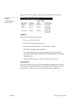
Wiring guidelines
Wire size
Maximum wiring
length
18 AWG
234 feet
20 AWG
148 feet
22 AWG
92 feet
24 AWG
58 feet
If you install the color active or color active video touch panel farther away from
the control system than recommended in Figure 13, connect a 12 VDC power
supply as shown in the wiring diagrams in this section.
Preparing captive wires
You will need a wire stripper, soldering iron, and flat head screwdriver to prepare
and connect the captive wires.
1.
Strip 0.25 inch of wire insulation off all wires and apply a light coat of solder
to the ends using a soldering iron.
2.
Insert each wire into the appropriate opening on the connector according to
the wiring diagrams and connector types described in this section.
3.
Turn the flat head screws clockwise to secure the wire in the connector.
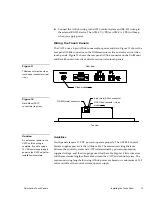
Using the AXlink 4-pin connector (UniMount and Rack-Mount)
Connect the control system’s AXlink connector to the AXlink connector (male) on
the rear panel of the CATP for data and 12 VDC power as shown in Figure 14.
PWR(+)
AXM
AXP
GND (-)
AXlink connector
Control system
PWR
AXM
AXP
GND
Black
Green
White
Red
Figure 13
Wiring guidelines
Caution
Do not over-torque the
screw. Doing so can bend
the seating pin and damage
the connector.
Caution
If you are using power from
AXlink, disconnect the wiring
from the AXCESS or
AXCENT2 Control System
before wiring the CATP.
Figure 14
AXlink wiring diagram
Summary of Contents for AXT-CV TiltScreen CATP
Page 8: ...vi Table of Contents Color Active Touch Panels ...
Page 130: ...122 Firmware Upgrades Color Active Touch Panels ...
Page 134: ...126 EXM 1 MB Memory Upgrade Color Active Touch Panels ...
Page 140: ...132 Technical Support Color Active Touch Panels ...
Page 144: ...136 Index Color Active Touch Panels X XE 44 ...


