


Color Active Touch Panels
Installing the Touch Panel
15
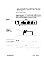
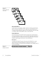
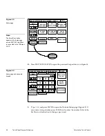
Using the AXlink 4-pin connector and external 12 VDC power supply
Connect the control system’s AXlink connector to the AXlink connector on the rear
panel of the CATP as shown in Figure 15.
PWR(+)
AXM
AXP
GND (-)
Control system
PWR
AXM
AXP
GND
12 VDC power supply
+
-
Black
Green
White
Black
Red
Use a 12 VDC power supply when the distance between the control system and
CATP exceeds the limits described in Figure 13. Make sure to connect only the
GND wire on the AXlink connector when using a 12 VDC power supply. Do not
connect the PWR wire to the AXlink connector’s PWR (+) terminal on the Control
System side of the connector.
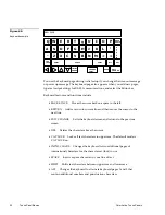
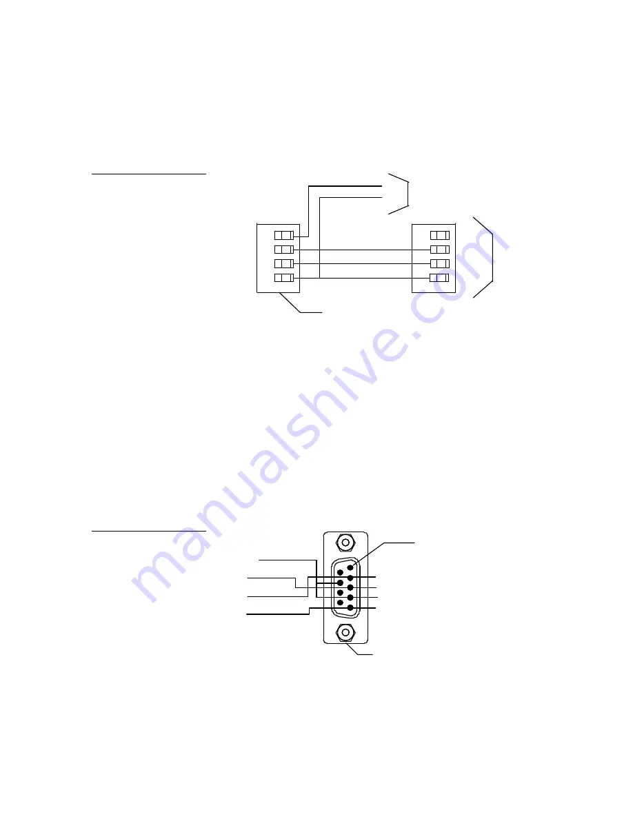
Using the RS-232 (DB9) connector for mouse control or data
The dual-function RS-232 (DB9) connector in the touch panels support most
standard serial mouse control devices and RS-232 communication protocols for PC
data transmission. Refer to Figure 16 for DB9 wiring diagram.
DB-9 connector (male)
TXD
RXD
GND
+12VDC
4 and 7 (+12)
3 (RXD)
5 (GND)
2 (TXD)
Pin 1
Figure 15
AXlink and 12 VDC power
supply wiring diagram
Figure 16
Circuit connector wiring
diagram
Summary of Contents for AXT-CV TiltScreen CATP
Page 8: ...vi Table of Contents Color Active Touch Panels ...
Page 130: ...122 Firmware Upgrades Color Active Touch Panels ...
Page 134: ...126 EXM 1 MB Memory Upgrade Color Active Touch Panels ...
Page 140: ...132 Technical Support Color Active Touch Panels ...
Page 144: ...136 Index Color Active Touch Panels X XE 44 ...