AMPEON AMP-Series
http://www.ampeon.cn
6
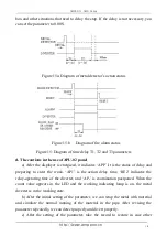
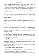
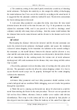
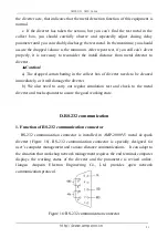
c. Section diagram of control box
Figure 5
:
Diagram of the inner units in control box
1.1 Explanation of main terminal-X1 electric wiring
Figure 6
:
Diagram of the main terminal-X1 wiring
a. The connectors 2# and 3# are the incoming line of power supply AC220V. We
should avoid the share of power supply with other equipments that may produce
interference radiation. If possible, please supply the electricity separately. It is
necessary to pay special attention to avoid the phenomenon that on the time of spark
alarm stopping, the power supply of instrument itself cannot be shut down. As the
equipment is installed to the metal pipe, it is recommended that you use the wire over
RVV 1.5mm
2
.
b. The connectors 4# and 5# can output AC220Vpower supply. It is connected to
the electromagnetic valve coil of the correlated diverter. As the equipment is installed
to the metal pipe, it is recommended that you use the wire over RVV 1.5mm
2
.
c. The connectors 6# and 7# can provide passive normally closed relay contact
and provide the input circuit to PLC in the control box of the control equipment. With
this, the system can stop when the fire alarm happens. Through the use of 7# and 8#
normally open contacts and with the transformation of intermediate relay, the blower
fan contactor can be directly controlled and the rapid stopping in case of fire alarm


