AMPEON AMP-Series
http://www.ampeon.cn
13
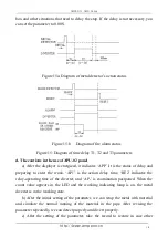
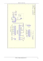
Figure 12: Diagram of diverter installing
C. Debugging and usage maintenance
1. Indicative and adjustable parameter of the control panel
After completing the installing, first carry out the energizing test. If the displayer
shows normally after the energizing, the following procedure is the understanding
and the setting of the parameters.
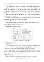
1.1 Spark inspection unit AMP-TIME SET
Figure 13: The diagram of parameter panel in spark inspection unit
a. The explanation of the messages in LCD
11:11:08
indicates
the real-time now is 11:11:08a.m.
♬
03
indicates
there are 3 alarm messages
AMPEON
indicates
Logo of Ampeon Electron Co., Ltd.


