11
Display1
Display 2
Display 3
Display 4
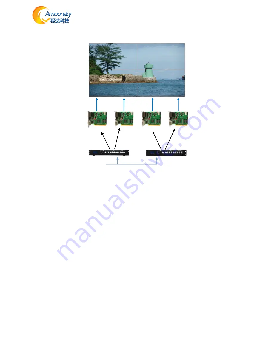
Figure 11 -Unequal Splicing
Steps:
1.Refer to Figure 14 Connect all devices.
2.Sending card S1 and S2 cascade, S3 and S4 cascade. Respectively adjustment LED screen software
Display 1 and Display 3 into a complete display area, Display 2 and Display 4 set another full display
area. (For details, please refer to the relevant suppliers of LED system operation)
3.Are provided P1 ~ P2 video processor parameters.
Processor P1
:
1.Setting resolution
Default Menu → Main Menu → OUTPUT →Resolution→1440x900 60Hz
Default Menu → Main Menu → OUTPUT→Width→1408
Default Menu → Main Menu → OUTPUT→Height→896
2. Setting splice
Default Menu → Main Menu →SPLICE→ MODE →V-Wall
Default Menu → Main Menu →SPLICE→ Pattern →Unequal
Default Menu → Main Menu →SPLICE→V-Wall Sync →On
Default Menu → Main Menu →SPLICE→Parameters→H Total→2688
Default Menu → Main Menu →SPLICE→Parameters→V Total→896
Default Menu → Main Menu →SPLICE→Parameters→H Start→0
Default Menu → Main Menu →SPLICE→Parameters→V Start→0
S1
S3
S4
S2
DVI-OUT
DVI-OUT
DVI -INPUT
P1
P2


