M370185-01
xvii
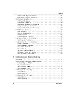
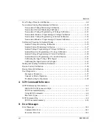
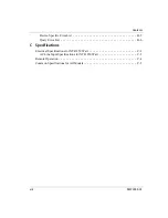
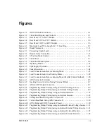
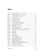
Table 1-1
XTR 850 Watt Series Voltage and Current Ranges - - - - - - - - - - - - - - - - 1–3
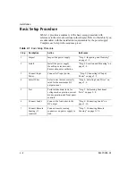
Table 2-1
Basic Setup Procedure - - - - - - - - - - - - - - - - - - - - - - - - - - - - - - - - - - - 2–2
Table 2-2
Current Carrying Capacity for Load Wiring - - - - - - - - - - - - - - - - - - - - - 2–6
Table 3-1
Select and Set from the Front Panel - - - - - - - - - - - - - - - - - - - - - - - - - - 3–3
Table 3-2
Front Panel Display Text - - - - - - - - - - - - - - - - - - - - - - - - - - - - - - - - - 3–9
Table 3-3
Shipped Configuration - - - - - - - - - - - - - - - - - - - - - - - - - - - - - - - - - - 3–16
Table 3-4
Alarm Order of Precedence - - - - - - - - - - - - - - - - - - - - - - - - - - - - - - - 3–19
Table 3-5
Alarm Mask Bit Positions - - - - - - - - - - - - - - - - - - - - - - - - - - - - - - - - 3–22
Table 3-6
Alarm Latch Bit Positions - - - - - - - - - - - - - - - - - - - - - - - - - - - - - - - - 3–23
Table 3-7
Power Cycle Saved/Recalled Settings - - - - - - - - - - - - - - - - - - - - - - - - 3–35
Table 3-8
User Accessible Saved/Recalled Settings- - - - - - - - - - - - - - - - - - - - - - 3–36
Table 3-9
Power Supply Default Settings- - - - - - - - - - - - - - - - - - - - - - - - - - - - - 3–40
Table 4-1
Monitor Lines - - - - - - - - - - - - - - - - - - - - - - - - - - - - - - - - - - - - - - - - - 4–3
Table 4-2
Remote Programming Options- - - - - - - - - - - - - - - - - - - - - - - - - - - - - - 4–4
Table 4-3
APG Pins and Functions J1 - - - - - - - - - - - - - - - - - - - - - - - - - - - - - - - - 4–5
Table 4-4
AUX Output and ISOL Connector Pins and Functions J3- - - - - - - - - - - 4–21
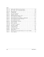
Table 5-1
Remote Control Connector Pins and Functions J4 and J6 - - - - - - - - - - - - 5–3
Table 5-2
DB-9 Pinouts - - - - - - - - - - - - - - - - - - - - - - - - - - - - - - - - - - - - - - - - - 5–4
Table 5-3
RJ-45 Pinouts - - - - - - - - - - - - - - - - - - - - - - - - - - - - - - - - - - - - - - - - - 5–4
Table 5-4
DB-25 Pinouts - - - - - - - - - - - - - - - - - - - - - - - - - - - - - - - - - - - - - - - - 5–5
Table 5-5
DB-9 Pinouts - - - - - - - - - - - - - - - - - - - - - - - - - - - - - - - - - - - - - - - - - 5–7
Table 5-6
RJ-45 Plug Pinouts - - - - - - - - - - - - - - - - - - - - - - - - - - - - - - - - - - - - - 5–7
Table 5-7
RJ-45 Plug on Slave Unit - - - - - - - - - - - - - - - - - - - - - - - - - - - - - - - - - 5–8
Table 5-8
Rules for Multichannel Responses - - - - - - - - - - - - - - - - - - - - - - - - - - 5–23
Table 5-9
Status Byte Summary Register- - - - - - - - - - - - - - - - - - - - - - - - - - - - - 5–28
Table 5-10
Standard Event Status Register - - - - - - - - - - - - - - - - - - - - - - - - - - - - 5–32
Table 5-11
OPERation Status Register - - - - - - - - - - - - - - - - - - - - - - - - - - - - - - - 5–36
Table 5-12
OPERation SHUTdown Status Register - - - - - - - - - - - - - - - - - - - - - - 5–37
Table 5-13
OPERation SHUTdown PROTection Status Register - - - - - - - - - - - - - 5–37
Table 5-14
OPERation CSHare Status Register - - - - - - - - - - - - - - - - - - - - - - - - - 5–38
Table 5-15
QUEStionable Status Register - - - - - - - - - - - - - - - - - - - - - - - - - - - - - 5–45
Table 5-16
QUEStionable VOLTage Status Register- - - - - - - - - - - - - - - - - - - - - - 5–46
Tables
Summary of Contents for Soresen XTR 100-8.5
Page 2: ......
Page 16: ...xiv ...
Page 28: ...1 8 ...
Page 50: ...Local Operation 3 8 M370185 01 Figure 3 3 Front Panel Menu System ...
Page 93: ...Using Multiple Power Supplies M370185 01 3 51 3 ...
Page 94: ...Local Operation 3 52 M370185 01 ...
Page 128: ...Analog Programming APG and Isolated Analog Programming ISOL 4 34 M370185 01 ...
Page 198: ...Remote Operation 5 70 M370185 01 ...
Page 261: ...SCPI Command Tree M370185 01 A 35 A ...
Page 262: ...A 36 ...
Page 279: ...Index M370185 01 IX 3 described 3 7 3 36 number available 3 36 stored values 3 36 ...
Page 280: ...IX 4 ...

