15312
200 Series 36V
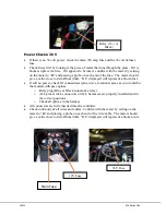
If it does not, check to be certain that the 36 volt circuit is wired properly.
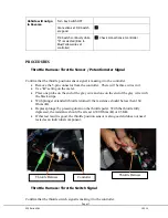
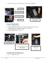
Power to Throttle Switch
Use “V” setting on the meter.
Place one probe on the white wire of the Throttle switch and one probe to a good
chassis ground such as the negative (-) post at the 350 amp fuse.
Turn the ignition key to the “ON” position.
The meter should read 12 – 14 volts.
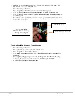
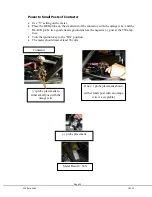
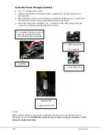
Controller Power from 36V Harness
Use “V” setting on the meter.
Meter Result
12 - 14V
(+) probe placement shown
(-) probe placement to any good
chassis ground
Safety Switch
(+) Probe Placement
>36 volts for the
battery system
(-) Probe Placement
To contactor
Main Fuse
Summary of Contents for 36V 200 Series
Page 1: ...15312 Service Manual 200 Series 36V...
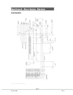
Page 12: ...Page 9 200 Series 36V 15312 Section 6 ELECTRICAL SYSTEM SCHEMATICS Figure 1 Vehicle Schematic...
Page 13: ...15312 200 Series 36V Figure 2 Motor Controller Schematic...
Page 18: ...Page 15 200 Series 36V 15312 Section 8 BRAKES BRAKE SYSTEM REPLACEMENT...


