


15312
200 Series 36V
Section 9 -
T
ROUBLESHOOTING
FLOWCHART
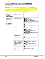
Follow the steps below to quickly diagnose common issues. For detailed testing
information, see Procedures below. It is strongly recommended to first check all
wiring connections and terminals to ensure that they are securely attached. Loose
connections are the most common cause for electrical issues.
Issue
Test Item
If Fail
Vehicle does not
move when
throttle depressed
Turn Key Switch ON
Having the throttle
depressed while
shifting from “F” to
“R” or visa-versa will
generate a fault.
Reset Key Switch to
resolve the fault.
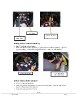
Battery Gauge turns ON
Check Main Fuse
Check 12V circuit Fuse
Check Yellow Body connector
Check for >12V at Key Switch Red and
Black on harness side
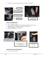
Relay “clicks” once
Check connections at Relay
Ensure 12V at Black wire when key ON
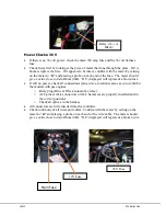
>36V at Orange Contactor
wires
Touch Pre-charge Resistor. If hot,
controller is bad. Disconnect Main
Fuse.
Check 36V circuit Fuse
Check for >36V at Purple wires at
Motor Controller
Check condition or all other connections
at controller
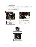
Turn Key Switch OFF
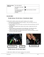
Throttle Switch continuity to
Ground with Throttle
depressed (white wire at
controller)
Check connections at Throttle Switch
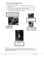
Throttle Sensor resistance
normally below 120Ω (Gray
to Gray/Black wires at
controller)
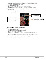
Check that Throttle Pedal has fully
returned
Inspect Throttle sensor closely for
cracks
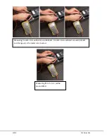
Throttle Sensor resistance
above 4300Ω when Throttle
depressed (Gray to
Gray/Black wires at
controller)
Check condition of connections at
Throttle Sensor
Check connection to harness
Summary of Contents for 36V 200 Series
Page 1: ...15312 Service Manual 200 Series 36V...
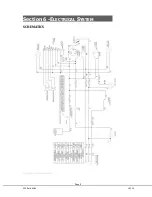
Page 12: ...Page 9 200 Series 36V 15312 Section 6 ELECTRICAL SYSTEM SCHEMATICS Figure 1 Vehicle Schematic...
Page 13: ...15312 200 Series 36V Figure 2 Motor Controller Schematic...
Page 18: ...Page 15 200 Series 36V 15312 Section 8 BRAKES BRAKE SYSTEM REPLACEMENT...


