15312
200 Series 36V
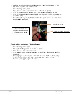
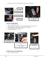
Remove the 5-pin connector from the controller. There will be three wires in it.
The throttle switch is an ON/OFF switch.
Use “Ω” setting on the meter.
Place one probe on the white wire and one on the chassis ground.
With the button pushed in (throttle fully returned) the meter should say “OL”.
With the button extended (throttle pressed), there should be a value shown close to
Zero Ohms (0Ω).
If this test result is good, the throttle switch is also good and does not need tested as
an individual component.
Throttle Position Sensor / Potentiometer
Use “Ω” setting on the meter.
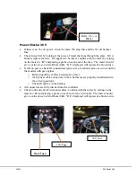
Unplug the throttle position sensor from the harness.
Place one probe on the end of each wire.
With plunger extended (throttle returned), the resistance should be less than 160
Ohms (Ω).
Depress plunger by pressing down on the throttle pedal. With the throttle fully
depressed, the resistance should be at least 4,300 Ohms (Ω) or 4.3KΩ.
If this does not happen, replace the sensor.
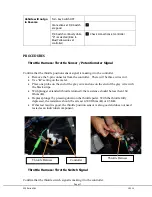
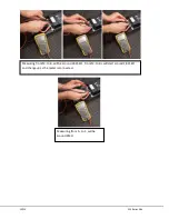
Probe Placement for
Throttle Harness Testing
of Safety Switch Signal
Throttle Harness
Nearest Chassis Ground
Summary of Contents for 36V 200 Series
Page 1: ...15312 Service Manual 200 Series 36V...
Page 12: ...Page 9 200 Series 36V 15312 Section 6 ELECTRICAL SYSTEM SCHEMATICS Figure 1 Vehicle Schematic...
Page 13: ...15312 200 Series 36V Figure 2 Motor Controller Schematic...
Page 18: ...Page 15 200 Series 36V 15312 Section 8 BRAKES BRAKE SYSTEM REPLACEMENT...

