21
To ensure proper unit grounding, the ground wire should run
from the furnace ground screw located inside the furnace junc
-
tion box all the way back to the electrical panel.
NOTE:
Do not
use gas piping as an electrical ground. To confirm proper
unit grounding, turn off the electrical power and perform the
following check.
1. Measure resistance between the neutral (white)
connection and any unpainted surface.
2. Resistance should measure 10 ohms or less.
This furnace is equipped with a blower door interlock switch
which interrupts unit voltage when the blower door is opened
for servicing. Do not defeat this switch.
24 Volt Thermostat Wiring
Low voltage connections can be made through either the right or
left side panel. Thermostat wiring entrance holes are located in
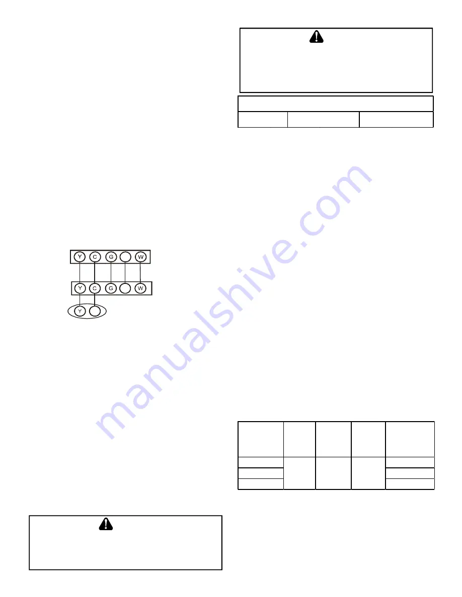
the blower compartment. The following figure shows connections
for a “heat/cool system”.
This furnace is equipped with a 40 VA transformer to facilitate
use with most cooling equipment. Consult the wiring diagram,
located on the blower compartment door, for further details of
115 Volt and 24 Volt wiring.
R
C
Furnace Integrated
Control Module
Remote Condensing Unit
(Single-Stage Cooling)
R
Room
Thermostat
Figure 28
Single-Stage Heating Thermostat Application
A single-stage thermostat with only one heating stage is
needed to control this furnace.
Fossil Fuel Applications
This furnace can be used in conjunction with a heat pump in a
fossil fuel application. A fossil fuel application refers to a combined
gas furnace and heat pump installation which uses an outdoor
temperature sensor to determine the most cost efficient means
of heating (heat pump or gas furnace).
Strictly follow the wiring guidelines in the fossil fuel kit installation
instructions. All furnace connections must be made to the furnace
integrated control module and the “FURNACE” terminal strip on
the fossil fuel control board.
Gas Supply and Piping
T
O
PREVENT
UNRELIABLE
OPERATION
OR
EQUIPMENT
DAMAGE
,
THE
GAS
MANIFOLD
PRESSURE
MUST
BE
AS
SPECIFIED
ON
THE
UNIT
RATING
PLATE
. O
NLY
MINOR
ADJUSTMENTS
SHOULD
BE
MADE
BY
ADJUSTING
THE
GAS
VALVE
PRESSURE
REGULATOR
.
CAUTION
WARNING
P
OSSIBLE
PROPERTY
DAMAGE
,
PERSONAL
INJURY
OR
DEATH
MAY
OCCUR
IF
THE
CORRECT
CONVERSION
KITS
ARE
NOT
INSTALLED
. T
HE
APPROPRIATE
KITS
MUST
BE
APPLIED
TO
ENSURE
SAFE
AND
PROPER
FURNACE
OPERATION
. A
LL
CONVERSIONS
MUST
BE
PERFORMED
BY
A
QUALIFIED
INSTALLER
OR
SERVICE
AGENCY
.
Natural Gas
Minimum: 4.5" W.C. Maximum: 10.0" W.C.
INLET GAS SUPPLY PRESSURE
TABLE 4
The furnace rating plate includes the approved furnace gas input
rating and gas types. The furnace must be equipped to operate
on the type of gas applied. This includes any conversion kits
required for alternate fuels and/or high altitude.
Inlet gas supply pressures must be maintained within the ranges
specified in table 4. The supply pressure must be constant
and available with all other household gas fired appliances
operating. The minimum gas supply pressure must be main
-
tained to prevent unreliable ignition. The maximum must not
be exceeded to prevent unit overfiring.
High Altitude Derate
GMES96-U furnaces do not use ID plugs, thus do not require
any ID plug changes.
The furnace, as shipped, requires no change to run between
0-4500 feet. At all altitudes the air temperature rise must be
within the range listed on the the Specification Sheet ap
-
plicable to your model for the fuel used. Manifold pressure
adjustments and combustion analysis are required for all
installations above 4500 ft. Refer to “Gas Supply Pressure
Measurement” section for instruction on how to properly
measure and adjust manifold “outlet” pressure. The furnace
should operate for a minimum of 15 minutes before taking a
combustion sample. Combustion samples should be taken
from beyond the furnace exhaust and must be within provided
CO2% range. See table 5 for recommended manifold pres
-
sure adjustments and proper CO2% range. Gas heating val
-
ues can vary; further pressure adjustment may be necessary
to ensure furnace operates within acceptable CO2 range.
MODEL
Manifold
Presure
at 5000ft
Manifold
Pressure
at 7500ft
C02%
Natural
Gas
Max Allowable
Venting (3 in
only)
*MES960403BU
100ft
*MES960603BU
100ft
*MES960805CU
80ft
2.5" w.c. 2.4" w.c.
6.5 - 8.5
TABLE 5
Gas Valve
This unit is equipped with a 24 volt gas valve controlled during
furnace operation by the integrated control module. Taps for
measuring the gas supply pressure and manifold pressure are
provided on the valve.
The gas valve has a manual ON/OFF control located on the valve


