22
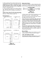
Timing Chart for Normal Integrated Ignition Control Operation
Timing Chart for Normal Cooling Operation
Seconds 0 5 0 45
Indoor Fan
Outdoor Fan
and
Compressor
Thermostat
On
Off
On
Off
On
Off
On
Off
Open
Closed
Closed
Open
On
Off
On
Off
On
Off
Seconds 0 17 20 23 53 0 5 60, 90, 120
or 180
Air Circulation
Blower
Gas Valve
Ignitor
Pressure Switch
Induced Draft Blower
Thermostat
Integrated Control
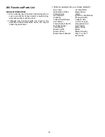
Diagnostic Light Signal Meanings
Light Signal
Refer To "Abnormal Operation -
Integrated Control" Section
Continuous Light
1. Internal Control Failure
1 Flash
2. System Lockout
2 Flashes
3. Pressure Switch Stuck Closed
3 Flashes
4. Pressure Switch Stuck Open
4 Flashes
5. Open Limit Control
5 Flashes
6. Open Roll-Out Control
Continuous Flashing
7. Flame Sensed No Call For Heat


