27
With Power and Gas Off
1. Connect a water manometer or adequate gauge to
the inlet pressure tap of the gas valve. (Figures
27, 28 or 29.)
As an alternative method, inlet gas pressure can also
be measured by removing the cap from the dripleg and
installing a predrilled cap with a hose fitting.
With Power and Gas On
2. Put furnace into heating cycle and turn on all other
gas consuming appliances.
Inlet Gas Pressure
Natural
Min. 5.0" W.C., Max. 10.0" W.C.
Propane Min. 11.0" W.C., Max. 13.0" W.C.
Inlet Gas Pressure Must Not Exceed the Maximum Value Shown
in Table
If operating pressures differ from above, make necessary
pressure regulator adjustments, check piping size, etc.,
and/ or consult with local utility.
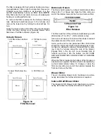
Figure 30
Measuring Inlet Gas Pressure
(Alternate Method)
Check Manifold Pressure
A tapped opening is provided in the gas valve to facilitate
measurement of the manifold pressure. (Outlet Pres-
sure Tap in Figures 27, 28 or 29) A U Tube manom-
eter
having a scale range from 0 to 12 inches of water
should be used for this measurement. The manifold
pressure must be measured with the burners operating.
To adjust the pressure regulator, remove the adjustment
screw cover on the gas valve. Turn out (counterclock-
wise) to decrease pressure, turn in (clockwise) to in-
crease pressure. Only small variations in gas flow should
be made by means of the pressure regulator adjust-
ment. In no case should the final manifold pressure vary
more than plus or minus 0.3 inches water column from
the specified pressure. Any major changes in flow should
be made by changing the size of the burner orifice.
GUD Manifold Pressure
WARNING
To prevent death or personal injury due
to carbon monoxide, all hoses must be
connected as shown in Figure 30. Fail-
ure to connect the hose between the
burner box and the pressure switch will
result in excessive levels of carbon mon-
oxide if the air inlet is blocked.
A Cap over adjustment screw must be in place when furnace is
operating.
To measure manifold pressure connect manometer between B and C.
B Hose between gas valve and air box (tee supplied by servicer).
C Tapped opening in manifold (hose barb supplied by servicer).
Figure 31
Measuring Manifold Pressure
(GUD Only)


