20
The
ground wire
should run all the way back to the
electrical panel. To confirm proper grounding:
1. Disconnect electrical power.
2. Measure resistance between the neutral (white) con-
nection and one of the burners.
3. Resistance should be 10 ohms or less.
On all units except GUD models, line voltage wiring
must enter through the left side of the furnace.
On GUD
models, line voltage wiring
must enter through the top or
left side of the furnace. Connect hot, neutral, and ground
wires as shown in the wiring diagram located on the
blower door of the unit. The ground screw is located
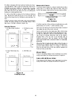
inside the junction box. (Figure 20)
Ground
Screw
Line
Voltage
Connections
Figure 20
Field Wiring Connections - GUD
(Line Voltage)
(Shown with Junction Box Cover Removed For
Clarity Only)
lX. Electrical Wiring
WARNING
To avoid the risk of electrical shock,
wiring to the unit must be properly po-
larized and grounded.
WARNING
To avoid electrical shock, injury or death,
disconnect electrical power before
changing any electrical wiring.
CAUTION
Label all wires prior to disconnection
when servicing controls. Wiring errors
can cause improper and dangerous op-
eration. After servicing is completed, al-
ways verify proper operation.
The wiring harness on this unit is furnished as an inte-
gral part of the furnace. Field alteration to comply with
electrical codes should not be required.
Line Voltage Wiring
Power supply to the furnace must be N.E.C. Class 1,
and must comply with all applicable codes. The furnace
must be electrically grounded in accordance with the
local codes or, in their absence, with the latest edition of
the National Electrical Code, ANSI NFP No. 70 and/or
the CSA C22. 1 Electrical Code. A fused disconnect
should be provided and sized in accordance with the
unit maximum overcurrent protection.


