15
VII. Condensate Piping
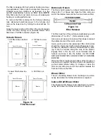
Figure 12
Standpipe Assembly
The Air Command 90 and 95 achieves its high effi-
ciency by condensing some of the flue products into a
slightly acidic water which must be piped to a drain. A
standpipe, which is shipped with the furnace, must be
installed on the right side of the furnace cabinet (Figure
12). The condensate from the recuperative coil and the
induced draft blower flows into this standpipe which acts
as a trap. No other trap may be used. A 3/4 inch PVC or
CPVC pipe must be run from the side of the standpipe
to a drain, maintaining a horizontal downward slope in
accordance with good plumbing practices. Do not trap
this line.
PVC or CPVC pipe is recommended since it is corro-
sion resistant, rigid, and not easily damaged. The drain
line must not be routed outside where it could freeze
and become blocked. The top of the standpipe must be
left open so any blockage in the drainline will be re-
lieved out the tip of the standpipe and not back up into
the unit.
If an air conditioning coil is installed with the furnace, a
common drain may be used (install as shown in Figure
13). Leaving an open tee near the cooling coil will allow
positive air pressure in the supply air plenum be relieved
out the tee without interfering with draining of the furnace
condensate.
Figure 13
WARNING
To prevent death, personal injury or prop-
erty damage, solvent cements are com-
bustible liquids and should be kept away
from all ignition sources. (ie. sparks, open
flames and excessive heat). Avoid breath-
ing cement vapors or contact with skin
and eyes.
Under some conditions, insulation of some or all of the
vent pipe and/or combustion air pipe may be required.
Do not install insulation until after the flue system has
been inspected for leaks as described below.
WARNING
To prevent death, personal injury or prop-
erty damage due to carbon monoxide,
carefully inspect the entire flue system
both inside and outside the furnace after
installation is completed, to assure it is
properly sealed and not leaking flue
gases.
For each 2 inch pipe, drill a 2-3/8 inch diameter hole
through the wall at the proper location.
For each 3 inch pipe, drill a 3-1/2 inch diameter hole
through the wall at the proper location.
Cut a piece of PVC (ABS) pipe that is the thickness of
the wall plus the depth of the sockets of the fittings to be
installed on the inside and outside of the walls.
To prevent the vent pipe from moving, and possibly
damaging the connections, locate the fittings on the
inside wall and the elbow on the outside as shown in
Figure 11 for the air intake.
In a basement installation, the pipes may be run be-
tween the joist spaces. If the pipes must go below the
joists, then the pipes must run up into the last joist
space to go through the header. Two 45° elbows should
be used rather than 90s. The horizontal run of exhaust
pipe must not have any sag that can hold condensate
and should reach up at least 1/4 inch per foot so that
condensate will run back to the unit to drain. Support
the horizontal run at least every three feet.
Allow for some expansion and contraction from tem-
perature fluctuations. The normal direction changes
usually account for this, but if you have a long run
followed by a short offset of less than 40 inches such as
going up into the last joist space, the pipes should be
tightly clamped to prevent flex loading on the fittings.
Seal around the pipe on the outside wall with silicone
caulking material.


