Always
O
n UPS Systems
M0309_N_Series_ABS_700-3kVA_User_Manual V2.8 2012-06-12
4
2.3.
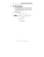
Description of Each Block
Input Breaker
: Prevents the breaker of the distribution panel from tripping when a
UPS fault or over-current condition occurs.
EMI/RFI Filter
: This filter attenuates the electrical noise associated with the
polluted utility power to the UPS or noise (THD) generated by the UPS.
Rectifier / Power Factor Correction (PFC)
: During normal operation, the
rectifier/power factor correction (PFC) circuit converts the utility power (AC power)
to DC power, which in turn is used by the inverter, while ensuring that the waveform
of the input current used by the UPS is close to ideal. This type of conversion and
technology maintains two key objectives: the utility power is used as efficiently as
possible, and the amount of distortion reflected back to the utility is minimized
therefore providing cleaner power to other devices in the building not being protected
by the N Series.
PFC Control:
By utilizing control circuits, the current drawn from the utility
power is in-phase with the input voltage. The control circuit also allows the
UPS to have a broader input voltage range (±25%).
Charger:
During normal operation, it converts AC voltage drawn from utility power
into regulated DC voltage, which charges or maintains the batteries at the desired
level by a float charge.
Batteries
: Sizes will vary in series and series-parallel configurations. Batteries are
Sealed Lead-Acid Valve regulated gel cells.
DC-to-DC Converter:
The converter utilizes energy from the battery system and
raises the DC voltage to the DC Bus operating voltage for the inverter. This allows
the inverter to operate continuously at its optimum efficiency and voltage, thus
increasing reliability.
Inverter
: The term inverter will denote the solid-state equipment and controls used
to convert power from the input rectifier or batteries to regulated pure sine wave AC
power for supporting the loads. The inverter will produce 50 or 60Hz (auto-
selectable) using Insulated Gate Bipolar Transistors (IGBT’s) switching at
approximately 18kHz, above the audible frequency range, and without low frequency
magnetic components. The inverter is of pulse width modulated (PWM) design
capable of providing the specified AC output with a very small tolerance (±2%), with
little to no distortion.
CPU/Control/User Interface
: The CPU controller monitors and maintains all
systems within the UPS while permitting communication between the UPS, user and
peripheral devices.
Static By-pass
: A static transfer switch and bypass circuit is provided as an integral
part of the UPS. The inverter has an overload rating of 125% rated load for one
minute, 150% rated load for 20 seconds, 200% rated load for one and a half cycles.
The static bypass will auto transfer to bypass if these overload conditions are
exceeded. The static transfer switch control logic will contain an automatic transfer
control that senses the status of the inverter logic signals, and operating and alarm
conditions. This control circuit will provide an uninterrupted transfer of the load to a
normal input source (or alternate bypass source). Transfers are made when an
overload or malfunction occurs within the UPS, without exceeding the transient limits
specified herein.

