background image

Q

_

P

D

S

_

D

M

_0

9

_V

1

.2


Smart Wi-Fi User Manual


18 

Smart Extender 

3.1.1 


LEDS AND BUTTONS 


Nominal  Modes 


Extender 
mode 

LED  

(from left to 

right) 

NAME 

EVENT 

STATE 

COLOR 


1  POWER 

while b 
driver boot 

Blinking ( 

(100 ms 

ON and 100 ms 
OFF)


White 


boot completed 

Fix 

White 


when downloading a 
FW 

Pulse : ALL LEDs are 
blinking at the same 
time!  
(normally is 
simultaneous with 
flashing: 100 ms ON 
and 100 ms OFF) 

White 


2  Wi-Fi 

Wifi ON - extender 
not yet on-boarded 

Slow blinking  (3s 
OFF and 100ms ON) 

RED 


Wifi ON - extender 
on-boarded with 
good BH link 

Fix 

White 


Wifi ON - extender 
on-boarded with 
poor BH link 

Slow blinking  (5s 
OFF and 100ms ON) 

White 


Wifi ON - extender 
on-boarded with no 
BH link 

Fix 

Red 


Wifi pausing OFF 

Off 

N/A 


3  WPS 

by default 

Off 


during paring 

Blinking 

(200 ms ON 

and 100ms OFF: 
broadcom default)


White 


paring successful 

Fix during 30 sec, 
then Off 

White 


WPS session overlap 

Fast blinking during 
2 minutes, then Off 

White 


Ethernet 
ports 


No link 

Off 

N/A 


Link 

Fix 

Green 


Link & Traffic 

Blinking 

Green 


Controller  
mode 

LED  

(from left to 

right) 

NAME 

EVENT 


1  POWER 

while b 
driver boot 

Blinking 

(100 ms ON 

and 100 ms OFF)


White 


boot completed 

N/A 


Summary of Contents for D2260G

Page 1: ...ALTICE LABS MANUAL Smart Wi Fi User Manual D2260G Version 1 3 2020 08 ...

Page 2: ......

Page 3: ...Q_PDS_DM_09_V1 2 Smart Wi Fi User Manual 3 Document s version history Document s version history Version Date Author Description 1 3 25 08 2020 Manuel Veríssimo Initial version ...

Page 4: ...tion or products referred to in the document This document is for information purposes only and does not constitute a legally binding offer The communication of the information contained in this document shall not oblige Altice Labs to supply the products and services identified and described herein Altice Labs reserves the right to effect changes to this document at any time and without prior not...

Page 5: ... OPERATION 24 3 3 2 1 Power on 24 3 3 2 2 Shut down 25 3 3 3 PUT THE SMART MESH IN Wi Fi NETWORK 25 4 User interface 26 4 1 Mobile application initial screen 26 4 2 Login 27 4 3 Initial Setup 27 4 3 1 Change name or password 28 4 3 2 Ready to Smart Wi Fi 28 4 3 3 Add extender 29 4 3 4 Find a place for extender 29 4 3 5 Good place for extender 30 4 3 6 Plug your extender 30 4 3 7 Connect the extend...

Page 6: ......

Page 7: ...ial screen 27 Figure 9 Change name or password 28 Figure 10 Ready to Smart Wi Fi 28 Figure 11 Add extender 29 Figure 12 Find a place for extender 29 Figure 13 Good place for extender 30 Figure 14 Plug your extender 30 Figure 15 Connect the extender 31 Figure 16 Name your extender 31 Figure 17 OnBording 32 Figure 18 Full Wi Fi coverage 32 Figure 19 Parental control 33 Figure 20 Guest Network 33 Fig...

Page 8: ......

Page 9: ...nternet Protocol version 4 IPv6 Internet Protocol version 6 ISP Internet Service Provider ITU T International Telecommunication Union Telecommunications LAN Local Area Network LED Light Emitting Diode MAC Media Access Control MAN Metropolitan Area Network MTBF Mean Time Between Failures OLT Optical Line Terminal ONT Optical Network Terminal PC Personal Computer PON Passive Optical Network PSK Phas...

Page 10: ...rence will not occur in a particular installation If this equipment does cause harmful interference to radio or television reception which can be determined by turning the equipment off and on the user is encouraged to try to correct the interference by one or more of the following measures Reorient or relocate the receiving antenna Increase the separation between the equipment and receiver Connec...

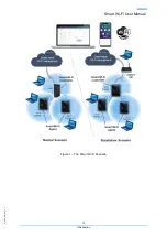
Page 11: ...for the in house Wi Fi coverage scenarios The solution incorporates hardware FGWs and Smart Wi Fi AP extenders a mobile user APP Android iOS and a unified web portal cloud based to configure manage and report the Wi Fi mesh ecosystem Both FGWs and Smart Wi Fi APs will run local software local Controller local Agent and a Smart Wi Fi Management agent supported on high performance state of the art W...

Page 12: ...ers Interoperable mesh solution compliant with Wi Fi Alliance Multi AP specification Optimal QoS and throughput performance High performance HW solution based on ultimate IEEE 802 11 standards Interoperable mesh solution compliant with Wi Fi Alliance EasyMesh Multi AP specification Cloud platform for central monitoring diagnostics and optimization of the Smart Wi Fi network Remote control of netwo...

Page 13: ...Q_PDS_DM_09_V1 2 Smart Wi Fi User Manual 13 Introduction Figure 1 The Smart Wi Fi Scenario ...

Page 14: ......

Page 15: ...n data flow topology and client roaming between APs 2 1 Management features 2 1 1 Customer Mobile APP Android and IOS APPs to configure and optimize the Wi Fi service User Cloud Access to the cloud with customer profile to have full visibility of Smart Wi Fi service performance Self Care Integration with self care applications that allows the configuration troubleshooting and management of Wi Fi s...

Page 16: ......
Page 17: ... hardware 3 1 INTERFACES LEDS AND BUTTONS Ethernet 2x GBE 10 100 1000 BASE T Wi Fi Dual band 2x2 2 4GHz 4x4 5GHz Physical buttons Power On OFF Reset CPU WPS LEDs Power led 1 x bi color backlit power button Wi Fi status 1 x tri color 2 4GHz and 5GHz status led WPS led 1 x bi color backlit status led ...

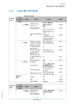
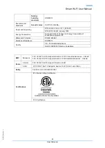
Page 18: ...nd 100ms ON RED Wifi ON extender on boarded with good BH link Fix White Wifi ON extender on boarded with poor BH link Slow blinking 5s OFF and 100ms ON White Wifi ON extender on boarded with no BH link Fix Red Wifi pausing OFF Off N A 3 WPS by default Off during paring Blinking 200 ms ON and 100ms OFF broadcom default White paring successful Fix during 30 sec then Off White WPS session overlap Fas...

Page 19: ...broadcom default White Ethernet ports No link Off N A Link Fix Green Link Traffic Blinking Green Alarm modes ALARM LED STATE Temperature WPS Fix Red Red Wi Fi nominal mode nominal color nominal color POWER Fix Red Red Firmware upgrade mode STEP LED STATE Download WPS Wi Fi Pulse Pulse White POWER Pulse Pulse White flashing WPS Wi Fi Blinking Blinking White POWER Blinking Blinking White Buttons man...

Page 20: ... is controller mode then change to extender mode Extender Power WPS Long 5s N A Controller Power WPS Long 5s N A 3 2 Technical Specifications Antenna Configuration Dual band 2x2 2 4GHz 4x4 5GHz Transmit power Max conducted 2 4 GHz up to 20dBm Max conducted 5GHz up to 30dBm Wi Fi support 802 11b g n ax 2 4GHz 802 11a n ac ax 5GHz Wi Fi Standards IEEE802 11 a b g n ac ax 802 11r Fast Roaming 802 11e...

Page 21: ...ems that allows the configuration Device Management Firmware upgrade inventory troubleshooting and management of remote actions device configurations and bulk Wi Fi service operations 3 2 1 Wi Fi Items Compliance Description IEEE 802 11 b g n ac Bit Rates 802 11 b g 1 2 5 5 6 9 11 12 18 24 36 48 and 54Mb s 802 11 n Up to 600Mb s over four spatial streams in the 2 4GHz band Up to 600Mb s over four ...

Page 22: ... 88dBm Mode g 10 PER 6Mb s 90dBm 12Mb s 89dBm 54Mb s 75dBm Mode n 2 4GHz 10 PER 1Mb s 96dBm 54Mb s 75dBm M0 20MHz 88 dBm M0 40MHz 85 dBm M7 20MHz 66 dBm M7 40MHz 63 dBm Mode n 5GHz 10 PER 6Mb s 89 dBm 54Mb s 74 dBm M0 20MHz 87 dBm M0 40MHz 83 dBm M7 20MHz 64 dBm M7 40MHz 61 dBm Mode ac 5GHz 10 PER M0 20MHz 87 dBm M0 40MHz 83 dBm M0 80MHz 80 dBm M9 20MHz 58 dBm M9 40MHz 55 dBm M9 80MHz 52 dBm 3 2 2...

Page 23: ...afety and Protection EN IEC 62368 1 Mechanical Resistance EN300019 Quality CE Conformité Européenne RoHS 2002 95 EC Directive Compliance EMC Emissions FCC CFR 47 Part 15 Subpart B Section 15 107 Conducted Emissions Class B FCC CFR 47 Part 15 Subpart B Section 15 109 Radiated Emissions Class B Radio 2 4 GHz FCC CFR 47 Part 15 Subpart C Section 15 247 5 GHz FCC CFR 47 Part 15 Subpart E Section 15 40...

Page 24: ... Fi up and running 3 3 1 Package content Figure 3 Smart Wi Fi power supply 110V 12V 3 3 2 PUT THE Smart Wi Fi IN OPERATION 3 3 2 1 Power on a Connect the 110V 12V power supply between the Smart Wi Fi 1 and the 110V power outlet b Press the ON OFF button 2 to turn on the power ...

Page 25: ... Fi power on 3 3 2 2 Shut down Press the ON OFF button 2 to turn off the power 3 3 3 PUT THE SMART MESH IN Wi Fi NETWORK Press the WPS button 2 to connect to the Wi Fi network Press the WPS button on Smart Wi Fi and FiberGateway Figure 5 Connect Smart Wi Fi to the FiberGateway ...

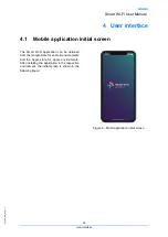
Page 26: ...itial screen The Smart Wi Fi application can be obtained from the Google store for android environments and the Apple store for Apple environments After installing the application in the respective environment the initial screen is shown in the following figure Figure 6 Mobil application initial screen ...

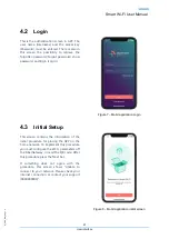
Page 27: ...e 7 Mobil application Login 4 3 Initial Setup This screen contains the information of the initial procedure for placing the APP on the home network To implement this procedure you must configure the Wi Fi parameters off the FiberGateway or read the QR code After this procedure press the Next bar If something does not agree with the procedure this screen shows Unable to connect to your network Plea...

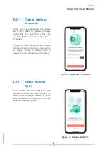
Page 28: ...screen If any of the information provided is invalid then the following information is displayed on the screen Unable to change name or password Special characters ar not allowed Figure 9 Change name or password 4 3 2 Ready to Smart Wi Fi In this screen we have access to three features Add Smart Wi Fi Add Extender get more information about Smart Wi Fi Learn more about Smart Wi Fi and start using ...

Page 29: ...andwidth throughput Improving Wi Fi coverage also improves bandwidth throughput To help in this choice will be used the smartphone which will show us three situations With the red color in the symbol appears the information The signal is bad here Try a better position With the yellow color in the symbol appears the Not only good Try a better position With the green color in the symbol appears the ...

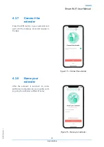
Page 30: ...oms away from the Gateway We can see the symbol in the app changing the color from red bad place for the extender to yellow not a very good place to green Ok this is a good place to put your extender Figure 13 Good place for extender 4 3 6 Plug your extender Plug your extender and wait until the led gets green Figure 14 Plug your extender ...

Page 31: ...the WPS button in your extender and wait until the message connected appear in the App Figure 15 Connect the extender 4 3 8 Name your extender After the extender is switched on some additional configurations are possible such as giving the extender a different name Figure 16 Name your extender ...

Page 32: ... Fi smart mesh application We can group these features into four groups Extended Wi Fi network network access control parental control guest network and user autonomy Figure 17 OnBording 4 4 1 Full Wi Fi coverage It is possible to analyze the Wi Fi signal in order to find areas without coverage in order to optimize the placement of extenders Figure 18 Full Wi Fi coverage ...

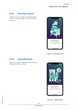
Page 33: ...4 2 Parental control Create your own profiles and quickly limit or check the internet usage of family members or groups Figure 19 Parental control 4 4 3 Guest Network Share your network with your guest without losing your device s privacy Figure 20 Guest Network ...

Page 34: ...e network characteristics of the devices and general information on data traffic The network topology shows the available Gateway and Extenders In the detail window there are eight buttons four on the bottom line Home Internet Devices Profiles and four on the top line Internet Pause Share Wi Fi Activate Guest Shortcuts It is possible to access more information by pressing the up symbol followed by...

Page 35: ...ou gain access to a set of features namely 1 Display of network speeds downward upward 2 Add a new extender 3 Available nodes 4 Connected devices 5 Access control and profiles 6 Restart network By restarting your gateway your network will be unavailable for about one minute You ll be patient and wait for the operation to be done until you can interact with Smart Wi Fi app Figura 24 Detalhe da rede...

Page 36: ... can select device by device or a global selection Note These features do not affect the device on which the Smart Wi Fi App is running Figura 25 Internet Pause 4 5 4 Share Wi Fi This screen shows the information needed to share access to the Wi Fi network The information is shown using a QR code and also with the network name and password By pressing the Share bar you can access messaging applica...

Page 37: ...ivate guest network This screen contains the functionality that allows the activation of guests on the network maintaining the privacy of the devices on the private network Guests only have access to the gateway s coverage area Figura 27 Ativar convidado ...

Page 38: ...Rua Eng José Ferreira Pinto Basto 3810 106 Aveiro Portugal Tel 351 234 403 200 Fax 351 234 424 723 ...

Page 39: ...o an outlet on a circuit different from that to which the receiver is connected Consult the dealer or an experienced radio TV technician for help FCC CAUTION The grantee is not responsible for any changes or modifications not expressly approved by the party responsible for compliance Such modifications could void the user s authority to operate the equipment IEEE 802 11b or 802 11g operation of th...

Reviews: