


Working examples
© ALTENDORF 2007
16
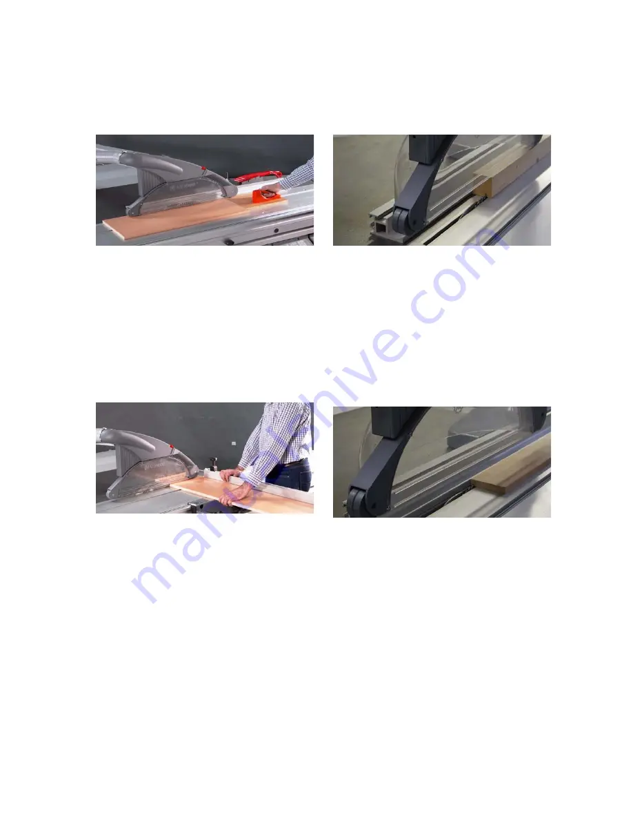
Cutting of strips
Fig. 3-9: Cutting of strips
Tool: Circular saw blade for fine cutting
Operation: Set the aluminum scale of the rip fence
to the lower guide surface. Place the workpiece on
the sliding table and use your left hand to push it
against the rip fence. Move the workpiece forward
with the sliding table, using the push block in the
area of the saw blade and continue to push the strip
until it is beyond the riving knife.
Crosscutting of wide workpieces
Fig. 3-10: Crosscutting
Tool: Circular saw crosscut blade
Operation: Place the workpiece against the mitre
fence, use the left hand to press it firmly against the
fence while moving it forward. When the flip stop is
used, this is to be flipped up before pulling the work-
piece back after cutting and the workpiece with-
drawn from the saw blade or the workpiece is only
to be removed beyond the rising blade tip.
Concealed cutting, rebating
Fig. 3-11: Concealed cutting
Tool: Circular saw blade for fine cutting
Operation: For rebating select the cutting sequence
so that the strip cut out falls away on the side of the
saw blade opposite to the fence. Lower the safety
hood onto the workpiece and ensure good work-
piece guidance (left hand pushes the workpiece
against the rip fence.)
Concealed cutting, routing
Fig. 3-12: Routing
Tool: Milling router permitted for manual feeding
(maximum width 15 mm).
Operation: Close the table opening by a table strip
matched to the milling router. Set the tool to the
desired routing depth. Leave the riving knife and
the rear tool cover in place. On feeding push the
workpiece firmly onto the table (otherwise there is
the danger of an unintentional insert process)
For crossrouting of narrow workpieces always
use the mitre fence.


